


R8182D,E,F,H,J COMBINATION PROTECTORELAY™ AND HYDRONIC HEATING CONTROLS
68-0105—2 12
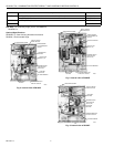
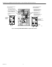
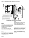
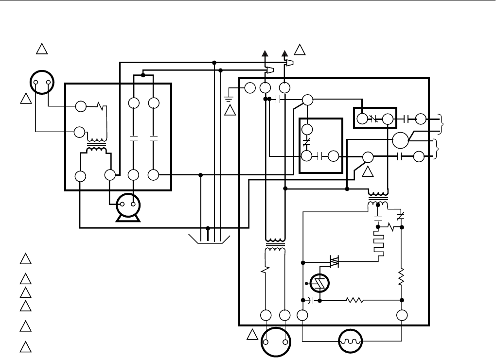
Fig. 17. R8182D and R845A in a typical multiple circulator zoning application.
OPERATION
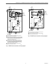
R8182D
A call for heat by the thermostat pulls in relay 1K, which
energizes the safety switch circuit and relay 2K to turn on the
burner. Safety switch starts to heat. If burner ignites within
safety switch timing, the cadmium sulfide flame detector sees
flame and the safety switch heater circuit is bypassed. The
burner operates until the call for heat is satisfied. The
circulator operates when relay 1K pulls in only if R to W is
made in the Aquastat¨ limit.
When R to B (low limit) is made by a drop in water
temperature, it acts as a call for heat, pulling in relay 2K to
turn on the burner. The circulator cannot operate. See Fig. 11,
16, 17 and 19.
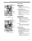
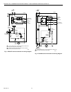
R8182E
The burner and circulator operate whenever the thermostat
calls for heat. Relay 2K pulls in. When the cadmium sulfide
flame detector sees flame, the safety switch heater circuit is
bypassed, and 2K is held in through 2K1. If temperature rises
to a high limit setpoint, R to B breaks, shutting off the burner.
The circulator continues operation under the thermostat
direction. See Fig. 12, 16, 17 and 20.
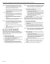
R8182F
The thermostat call for heat pulls in relay 2K to turn on the
burner. When the cadmium sulfide the flame detector sees
flame, safety switch the heater circuit is bypassed. The
circulator is independent of the thermostat circuit, being
controlled only by the Aquastat¨ limit switch. See Fig. 13, 17
and 20.
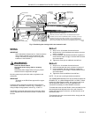
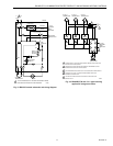
R8182H
A call for heat by the thermostat pulls in relay 1K, which
energizes the safety switch circuit and relay 2K to turn on the
burner. The safety switch starts to heat. If the burner ignites
within the safety switch timing, the cadmium sulfide flame
detector sees the flame and the safety switch heater circuit is
bypassed. The burner shuts Off when a call for heat is
satisfied. The circulator operates when relay 1K pulls in only if
R to W in the Aquastat¨ limit is made.
When R to B (low limit) is made by a drop in water
temperature, it acts as a call for heat, pulling in relay 2K to
turn on the burner. The circulator cannot operate. See Fig. 14,
16, 17 and 18.
M4521
L1
(HOT)
L2
1
5
4
6
3
2
1
2
4
3
6
5
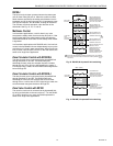
120 VAC POWER SUPPLY. PROVIDE DISCONNECT
MEANS AND OVERLOAD PROTECTION AS REQUIRED.
THERMOSTAT HEAT ANTICIPATOR SETTING, 0.2 AMP FOR R8182D.
THERMOSTAT HEAT ANTICIPATOR SETTING, 0.4 AMP FOR R845A.
CONTROL CASE MUST BE CONNECTED TO EARTH
GROUND. USE GROUNDING SCREW PROVIDED.
R8182E,H,J CONNECTIONS FROM ZC AND ZR ARE IDENTICAL
FOR MULTIPLE CIRULATOR ZONING APPLICAITON.
EACH ADDITIONAL ZONE REQUIRES A SEPARATE,
FIELD-ADDED 24V THERMOSTAT AND R845 RELAY.
24 VOLT
THERMOSTAT
B2
C2
C1
ZR
ZC
B1R
B
HIGH LIMIT
1K1
1K2
2K1
1K
1K1
1K2
B
R
W
LOW
LIMIT
1K
2
1
G
T T F F
R8182D
2K
2K2
BILATERAL
SWITCH
CIRCULATOR
C554A
R2
C1
S.SW
CONTACTS
SAFETY
SWITCH
HEATER
TRIAC
R1
TO WATER
CIRCULATO
R
TO OIL
BURNER
AND
IGNITION
BLUE
2
1
T
T
5 3
6 4
ZONE 2
THERMOSTAT
R845A
SWITCHING
RELAY ZONE 2
ZONE 2
CIRCULATOR
TO ADDITIONAL
ZONES 3, 4, ETC.