


R8182D,E,F,H,J COMBINATION PROTECTORELAY™ AND HYDRONIC HEATING CONTROLS
13 68-0105—2
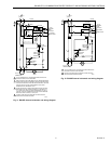
R8182J
The burner and circulator operate whenever the thermostat
calls for heat. Relay 2K pulls in. When the cadmium sulfide
flame detector sees flame, the safety switch heater circuit is
bypassed, and 2K is held in through 2K1. If temperature rises
to a high limit setpoint, R to B breaks, shutting off the burner.
The circulator continues operation under direction of the
thermostat. See Fig. 15, 16, 17 and 19.
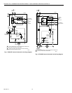
Multizone Control
In all multizone applications, a call for heat in any zone
energizes the safety switch circuit and relay 2K pulls in. If the
burner ignites within the safety switch timing, the cadmium
sulfide flame detector sees flame and the safety switch heater
is bypassed.
In all multizone applications with R8182D and H, the low limit
control in the Aquastat® limit acts independently to turn on the
main burner on a drop in water temperature. When R to B (low
limit) is made, relay 2K pulls in to turn on the main burner, the
same as for single-zone application.
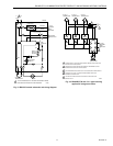
Zone Circulator Control with R8182D,H
The relay for each zone is connected to the Aquastat® limit
through terminals ZC and ZR. The R845 Relay and
thermostat for each zone can energize the zone circulator
through ZC only if R to W in the Aquastat® limit is made. If
R to B (high limit) is made, the zone thermostat energizes the
burner through ZR.
Zone Circulator Control with R8182E,J
The relay for each zone is connected to the Aquastat® limit
through terminals ZC and ZR. The R845A Relay and
thermostat in each zone can energize the zone circulator
through ZC on a call for heat. If R to B (high limit) is made, the
zone thermostat energizes the burner through ZR.
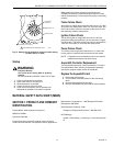
Zone Valve Control with R8182
The valve for each zone is connected to the Aquastat® limit
by wiring end switches on the zone valve to T-T on the R8182.
On a call for heat from any zone, the R8182 operates the
same as for single zone applications.
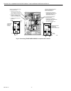
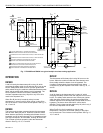
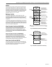
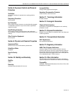
Fig. 18. R8182D,H Aquastat® limit switching.
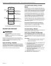
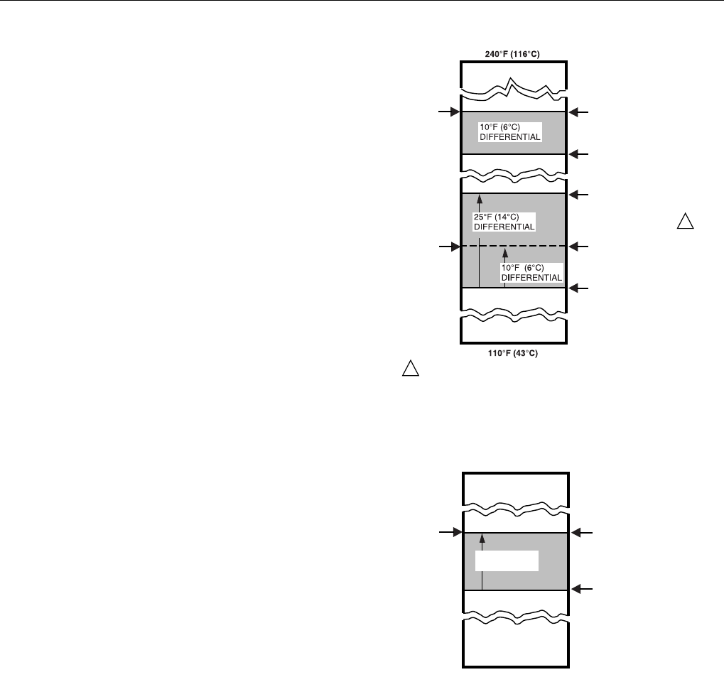
Fig. 19. R8182E,J Aquastat® limit switching.
LOW LIMIT
AND
CIRCULATOR
SETTING
H
IGH LIMIT
S
ETTING
SWITCH BREAKS ON
TEMPERATURE RISE.
BURNER TURNS OFF.
CIRCULATOR OPERATES
ON A CALL FOR HEAT.
SWITCH MAKES ON
TEMPERATURE FALL.
BURNER OPERATES ON
A
CALL FOR HEAT.
SWITCH MAKES R-W
AND BREAKS R-B ON
TEMPERATURE RISE.
SWITCH MAKES R-B AND
BREAKS R-W ON
TEMPERATURE FALL.
BURNER IS ON TO
MAINTAIN MINIMUM
WATER TEMPERATURE.
CIRCULATOR IS OFF.
M1523
SWITCH MAKES R-W
AND BREAKS R-B ON
TEMPERATURE RISE.
WHEN WATER REACHES PROPER TEMPERATURE, THE BURNER
SHUTS OFF OR THE CIRCULATOR PUMP STARTS (WHEN CALLING
FOR HEAT).
1
1
R-B MAKES ON
TEMPERATURE FALL.
BURNER AND
CIRCULATOR OPERATE
ON A CALL FOR HEAT.
180°F (82°C)
240°F (116°C)
M1510
R-B BREAKS ON
TEMPERATURE RISE.
BURNER TURNS OFF.
CIRCULATOR OPERATE
S
ON A CALL FOR HEAT.
H
IGH LIMIT
S
ETTING
15°F (8°C)
DIFFERENTIAL