


9 60-1165—6
9. Firmly tighten the mounting screw.
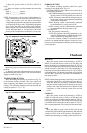
10. If the HEAT and COOL levers are to be locked in
place at a specific temperature, use the two insulated head
screws supplied instead of the two adjustable lever stop
brackets.
CAUTION
Do not use standard screws that provide metal-to-
metal contact with the stop brackets. Short circuit
and potential equipment damage may result.
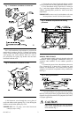
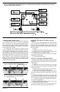
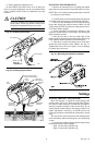
Fig. 19—Installing brass insert.
LED WINDOW
BRASS INSERT
INSERT HOLE
BACK OF
THERMOSTAT
M955A
Fig. 20—Installing stop brackets.
MOUNTING THE THERMOSTAT
1. Remove the thermostat cover by pulling the bottom
edge of the cover upward until it snaps free of the cover clip.
NOTE: The cover is hinged at the top and must be removed
by pulling up at the bottom.
2. Carefully remove and discard the polystyrene packing
insert that protects the mercury switches during shipment.
3. Turn over the thermostat base and note the spring
fingers that engage the subbase contacts. Make sure the
spring fingers are NOT bent flat, preventing proper electri-
cal contact with the subbase.
4. Set the adjustable heat anticipator indicators to the
respective current setting for each stage. See Setting the
Heat Anticipator section.
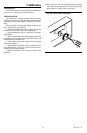
5. Note the two tabs on the top inside edge of the
thermostat base. The tabs fit into corresponding slots on top
of the subbase. Mount the thermostat on the subbase.
6. Align the two captive mounting screws in the ther-
mostat base with the posts on the subbase. See Fig. 21.
Tighten both screws. Do not overtighten screws or damage
to subbase posts can result.
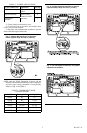
Fig. 21—Mounting thermostat on subbase.
Settings
SETTING THE HEAT ANTICIPATOR
Move the indicator to match the current rating of the
primary contro. See Fig. 22. When using the T874 Thermo-
stat with two stages of heating, set each heat anticipator to
match its respective primary control current draw. If you
cannot find the current rating on the primary control, or if
further adjustment is necessary, see NOTE and use the
following procedure to determine the current draw of each
stage.
The current draw must be measured with the thermostat
removed from the subbase and the power on to the heating
system.
1. Connect an ac ammeter of appropriate range between
the heating terminals of the subbase:
Stage 1: between W1 and RH or R.
Stage 2: between W2 and RH or R.
HEAT
LEVER
HOLES FOR INSULATED
LOCKING LEVER SCREWS
COOL
LEVER
HOLE WITH
BRASS INSERT
BRACKET
TABS
ADJUSTABLE
LEVER STOP
BRACKETS
BRACKET
SLOTS
MOUNTING
SCREW
M18682