


2
60-1165—6
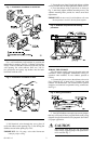
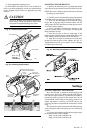
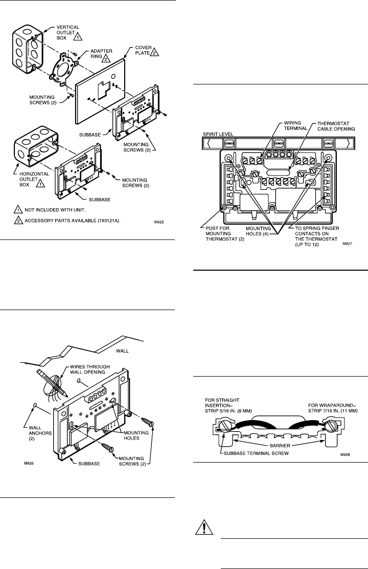
Fig. 1—Installation of subbase on outlet box.
2. Pull electrical wires through the cover plate (if
used) and subbase cable opening (Fig. 3). See Wiring the
Subbase section before pulling any wires.
IMPORTANT: Use 18 gauge, color-coded thermostat
cable for proper wiring.
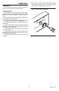
For a wall installation, hold subbase in position and
mark holes for anchors. See Fig. 2. Obtain wall anchors
locally. Take care that the wires do not fall back into the
wall opening. Set aside subbase. Drill two 3/16 in.
[4.8 mm] holes and gently tap anchors into the holes
until flush with the wall.
Fig. 2—Installation of subbase on wall.
WIRING THE SUBBASE
All wiring must comply with local electrical codes and
ordinances. Follow equipment manufacturer wiring in-
structions when available. To wire subbase, proceed as
follows:
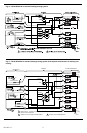
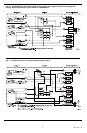
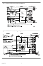
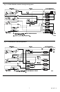
1. Connect the system wires to the subbase as shown in
Figs. 8 through 16. A letter code is located near each
terminal for identification. The terminal barrier permits
straight or conventional wraparound wiring connections.
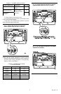
See Fig. 4.
Fig. 4—Wiring connections.
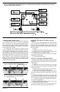
2. Your Q674 Subbase can require one or more jumpers
that may or may not be factory supplied. Refer to the wiring
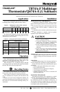
diagrams for specific terminals to be jumpered. See Table 3
for proper application.
CAUTION
Never install more than one wire per terminal
unless factory supplied jumper with spade termi-
nal is used. See Fig. 7.
3. Secure the cover plate (if used) and subbase with the
screws provided. Do not fully tighten the subbase screws.
4. Level the subbase using a spirit level, as shown in
Fig. 3, and firmly tighten subbase mounting screws. The
subbase mounting holes provide for minor out-of-level
adjustments.
IMPORTANT: An incorrectly leveled subbase will cause
the temperature control to deviate from setpoint.
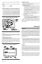
Fig. 3—Subbase components and leveling
procedure.