


3 60-1165—6
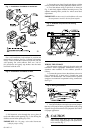
3. Firmly tighten each terminal screw.
4. Fit wires as close as possible to the subbase. Push
excess wire back into the hole.
5. Plug hole with nonflammable insulation to prevent
drafts from affecting the thermostat.
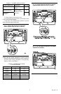
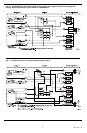
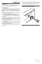
Fig. 5—Jumper RC and RH for single trans-
former system. Strip wire 3/4 in. [19 mm].
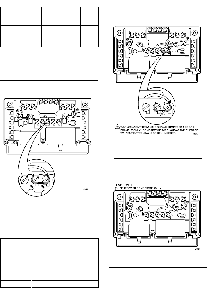
Fig. 6—Jumper adjacent terminals for special
system hookup. Strip wire 3/4 in. [19 mm].
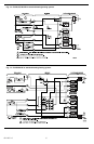
NOTE: Only the T874D Thermostat is shown with the
subbases. This thermostat/subbase provides 2-stage heat-
ing and 2-stage cooling connections. If using another
model, see Fig. 16 and Table 4.
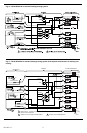
TABLE 4—THERMOSTAT BULB
CONFIGURATOIN.
Model No. Heating Bulbs Cooling Bulbs
T874A H1 C1
T874B H1 C1,C2
T874C H1, H2 C1
T874D H1, H2 C1, C2
T874E C1, C2
T874F H1, H2
Fig. 7—For nonadjacent terminals, use jumper
supplied with subbase.
TABLE 3—JUMPER APPLICATIONS.
If your subbase has: Application Use Fig.
RC, RH terminals single transformer 5
system
adjacent terminals special system 6
operation or LED
nonadjacent indication 7
terminals