1 60-1165—6
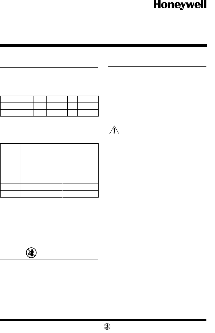
Q674 Switch Positions
Model System Fan
A Heat-Auto-Cool Auto-On
B Heat-Off-Cool Auto-On
C Off-Auto Auto-On
D None None
E Off-Heat-Auto-Cool Auto-On
G Off-Auto None
T874A-F Multistage
Thermostats/Q674A-E,G Subbases
TRADELINE
®
Installation Instructions for the Trained Service Technician.
Operation
On a 2-heat thermostat, the two stages of heat make
sequentially as the temperature drops. Make refers to the
mercury switch initiating a call for heat or cool.
There are about 2° F [1° C] between stages so that the
second stage makes only when the first stage cannot handle
the load. This is the interstage differential.
M3375
Recycling Notice
This control contains mercury in a sealed tube. Do not
place control in the trash at the end of its useful life.
If this control is replacing a control that contains mer-
cury in a sealed tube, do not place your old control in the
trash.
Contact your local waste management authority for
instructions regarding recycling and the proper disposal of
this control, or of an old control containing mercury in a
sealed tube.
Installation
WHEN INSTALLING THIS PRODUCT…
1. Read these instructions carefully. Failure to follow
them could damage the product or cause a hazardous condi-
tion.
2. Check the ratings given in the instructions and on the
product to make sure the product is suitable for your
application.
3. Installer must be a trained, experienced service tech-
nician.
4. After installation is complete, check out product
operation as provided in these instructions.
CAUTION
1. Disconnect power supply to prevent electrical
shock or equipment damage.
2. To prevent interference with the thermostat
linkage, keep wire length to a minimum and
run wires close as possible to the subbase.
3. Do not overtighten thermostat captive mount-
ing screws because damage to subbase threads
can result.
4. Do not short across coil terminals on heating
relay or gas control. This can burn out the
thermostat heat anticipator.
IMPORTANT: Thermostats are calibrated at the factory
by using subbases mounted at true level. Inaccurate
subbase leveling will cause thermostat control de-
viation.
LOCATION
Locate the subbase about 5 ft [1.5m] above the floor in
an area with good air circulation at average temperature.
Do not mount the subbase where the thermostat may be
affected by:
—drafts or dead spots behind doors and in corners.
—hot or cold air from ducts.
—radiant heat from sun, appliances or fireplace.
—concealed pipes and chimneys.
—unheated (uncooled) areas such as an outside wall
behind the thermostat.
MOUNTING THE SUBBASE
The thermostat subbase can be mounted on a vertical
outlet box, horizontal outlet box or directly on the wall.
1. If you must mount the subbase on a vertical outlet
box, order Honeywell 193121A Adapter Assembly (Fig. 1).
The assembly includes an adapter ring, two screws and a
cover plate to cover marks on the wall. Install the ring and
cover plate on the vertical outlet box.
J.H. • Rev. 5-94 • • ©Honeywell Inc. 1994 • Form Number 60-1165—6
Application
The T874A-F Thermostats provide 24 to 30 Vac control
for heating and/or cooling systems as listed in Table 1.
TABLE 1—THERMOSTAT HEATING AND/OR
COOLING STAGES.
The Q674A-E,G Subbases provide wiring terminals,
system and fan switching, and mounting bases for T874
Thermostats as listed in Table 2.
TABLE 2—SUBBASE SWITCHING POSITIONS.
T874 A B C D E F
Heating Stages 1 122—2
Cooling Stages 1 2122—
M3375


