


EGPWS LINE MAINTENANCE MANUAL
CAGE CODE: 97896 SCALE: NONE SIZE: A DWG NO.: 060-4199-180 REV: G SHEET 16 of 68
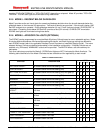
The Obstacle Database (in MK V and MK VII -204-204 and later, and MK VI, MK VIII and MK XXII) is a separate file
included within the terrain database. Both files are loaded into the EGPWS in the terrain database PCMCIA card.
The obstacle database is accessed by the EGPWC application software only if obstacle alerting is enabled by
installation configuration. The obstacle data is processed by the EGPWS in the same fashion as terrain, and is
presented on the display as terrain (uses same coloring scheme).
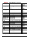
MK V, MK VII, and MK VIII EGPWS utilize a worldwide Terrain Database. The MK VI EGPWS utilizes a regional
Terrain Database consisting of one of the following regions:
• the Americas Region (designated “N”) for all of North, Central, and South America,
• the Atlantic Region (designated “A”) covering Greenland, Europe, Africa, and Asia,
• the Pacific Region (designated “P”) covering Europe, East Africa, Asia, Australia, the Pacific Ocean (to 120W
longitude including most of the US west coast).
The MK XXII utilizes 11 regional databases. For either worldwide or regional Terrain Databases, the Obstacle
Database currently covers cataloged obstacles (see Section 1.3) that are 100 feet high or higher. The MK XXII
database of obstacles is unique in the inclusion of oil rigs.
2.2.11 PEAKS DISPLAY MODE (OPTIONAL)
As an enhancement to the “standard” EGPWS terrain display, the Peaks Mode (when enabled by the installation
configuration) allows terrain below the aircraft to be viewed on the EGPWS terrain display during all phases of flight
(for MK V and MK VII -206-206 and later, and MK VI, MK VIII, and MK XXII). At altitudes safely above terrain for the
chosen display range, the terrain is displayed independent of aircraft altitude emphasizing the highest and lowest
displayed elevations to provide enhanced situational awareness. This can be particularly valuable to the flight crew
in case of an unplanned descent or off-route deviation and for previewing terrain prior to or during descent.
The EGPWS terrain display uses colors and shading patterns corresponding to the vertical displacement between
terrain elevation and the current altitude of the aircraft. With the “standard” display, terrain more than 2000 feet
below the aircraft is not displayed typically leaving the terrain display blank during the enroute portion of flight. The
Peaks Mode Display adds additional density patterns and level thresholds based on terrain elevations relative to the
range and distribution of terrain in the display area. The Peaks Mode is thus a “merged” display applicable to all
phases of flight.
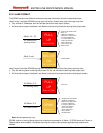
Within the Peaks Mode display, two elevation numbers indicate the highest and lowest terrain currently being
displayed. The elevation numbers indicate terrain in hundreds of feet Above Sea Level (ASL). The terrain elevation
numbers are displayed with the “highest” terrain number on top, and the “lowest” terrain number beneath it. The
“highest” terrain number is shown in the same color as the highest terrain color pattern on the display, and the
“lowest” terrain number is shown in the color of the lowest terrain color pattern shown on the display. A single
elevation number is displayed when there is no appreciable difference in terrain elevations such as when flying over
water (displayed blue on some display systems) or flat terrain. The elevation numbers on the display are also an
indication that the terrain display is selected.
2.2.12 GEOMETRIC ALTITUDE (GPS REQUIRED)
Geometric Altitude (for MK V and MK VII -206-206 and later, and MK VI, MK VIII, and MK XXII) is a computed
pseudo-Corrected Barometric Altitude (computed altitude “Above Sea Level” - ASL). This is designed to ensure
optimal operation of the EGPWS enhanced functions through all phases of flight and atmospheric conditions.
Geometric Altitude uses GPS Altitude, an improved pressure altitude calculation, Radio Altitude, and Terrain and
Runway elevation data to reduce or eliminate errors potentially induced into Corrected Barometric Altitude by
temperature extremes, non-standard altitude conditions, and altimeter miss-sets. Geometric Altitude also allows
continuous EGPWS operations in QFE environments without custom inputs or special operational procedures.
2.2.13 WEATHER RADAR AUTOTILT (MK V AND MK VII ONLY)
MK V and MK VII EGPWS (-210-210 and later) provide an automatic Weather Radar tilt angle capability. The Auto-
Tilt function uses aircraft altitude above the terrain and the terrain database to generate an optimum tilt angle for the
Weather Radar. The Auto-Tilt angle results in minimum ground clutter on the display while maintaining the optimum
weather detection capability. With manual tilt control, there can be over-scan where weather cells and terrain are