


L91A,B,D PROPORTIONING PRESSURETROL
®
CONTROLLERS
9 60-2152—08
SERVICE INFORMATION
CAUTION
Electrical Shock Hazard
1. Only qualified service technicians should attempt to
service or repair flame safeguard controls and
burner systems.
2. Disconnect power supply before cleaning the
potentiometer windings or wiper, or before replacing
the controller potentiometer.
Calibration
All controllers are carefully tested and calibrated at the factory
under controlled conditions. If the actual operating pressure
does not match the setpoint, move the main scaleplate slightly
up or down until the setpoint agrees with the actual pressure.
Maintenance
Keep the cover of the controller in place at all times to protect
the internal components from dirt, dust, and physical damage.
Perform routine maintenance occasionally by inspecting and
blowing or brushing away any accumulated dirt and dust. To
assure proper functioning of the controller at all times, perform
an operational check of the entire system during routine
maintenance checks. Be sure to handle controllers carefully at
the time of installation, during actual use, and during
maintenance.
Cleaning the Potentiometer Windings
or Wiper
Occasionally, the windings or wiper on the potentiometer (two
on the L91D) may need cleaning. Disconnect the power supply
before removing the cover from the controller and before
cleaning the potentiometer.
IMPORTANT
1. Use an electrical contact cleaner that does not con-
tain solvents.
2. Use extreme care to avoid bending the wiper arm,
changing the wiper tension and damaging the potenti-
ometer windings.
3. Do not use an abrasion or burnishing tool to clean the
potentiometer windings or wiper.
4. Do not use hard paper, such as a business card, or
abrasive materials (sandpaper, emery boards, file,
etc.) to clean the windings or wiper.
Solvent-type electrical contact cleaners can deteriorate plastic
components and wire insulation and leave an oily residue that
accumulates particulate matter (dust, etc.). The residue can
break down to form various carbonaceous substances that
cause early potentiometer failure.
Use of abrasive materials results in wearing of the
potentiometer windings and accumulation of particulate matter
that changes the resistance between the windings and the
wiper.
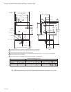
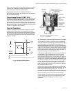
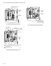
Replacing the Controller
Potentiometer (Fig. 8–10)
IMPORTANT:
1. Replace the controller potentiometer only when nec-
essary to obtain proper operation.
2. When replacing the potentiometer, be very careful not
to bend or damage the wiper arm, and not to change
the wiper tension. Any damage or change in tension
will decrease the life of the new potentiometer.
1. Disconnect all power to the controller.
2. Loosen the cover screw below the main scaleplate and
remove the cover.
3. Mark the wires to the external device (motor or valve
actuator) and disconnect them from the terminal block.
4. Remove the screw holding the terminal block bracket to
the top of the case (Fig. 8). Put this screw in a safe place
because it will be needed later.
5. While careful not to damage the potentiometer wiper or
any of the internal wiring, lift out the terminal block and
bracket.
6. Before removing any potentiometer wires, carefully note
and record (sketch) the position (off-center) of the active
winding on the potentiometer and the location and con-
nections of all wiring terminals. The new potentiometer
must be inserted and connected the same.
Example: In Fig. 9, the active winding is on the left half of
the potentiometer; the wire from the left end of the wind-
ing is connected to the (W) terminal on the terminal
block, and the wire from the right end of the winding is
connected to the (B) terminal on the terminal block.
7. Loosen the (W) and (B) screws on the terminal block,
and remove the two wires to the active winding of the
potentiometer. Leave the wire to the wiper arm intact.
8. Carefully unscrew the bolt that holds the potentiometer
to the bracket. Make sure the potentiometer wires do not
entangle with the wiper and bend it.
9. Carefully slide the old potentiometer off the bolt.
10. Carefully slide the bolt through the new potentiometer.
Make sure that:
a. The off-center position of the winding on the new
potentiometer is the same as the old potentiometer.
(Consult sketch in step 6.)
b. The wiper will contact bare wires. (Rotate the potenti-
ometer on the bolts so the surface of the winding
where the brown enamel was removed is toward
you.)
11. Screw the bolt into the potentiometer bracket. Make sure
the wiper is contacting bare wires (step 10.b); then
tighten the bolt.
12. Connect the two potentiometer wires to the (W) and (B)
terminals on the terminal block and tighten the screws.
Make sure these wires are connected to the same termi-
nals as in the old potentiometer. (Consult sketch in step
6.)
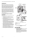
13. Carefully fit the hole in the bottom of the terminal block
bracket over the screw protruding upward from the bot-
tom of the case (Fig. 10). Insert the screw (removed in
step 4) through the hole in the top of the case (Fig. 8)
and into the top of the bracket, and tighten it.
14. Reconnect the wires from the external device (motor or
actuator) to the terminal block.
15. Replace the cover and tighten the cover screw.
16. Reconnect power to the controller.