


L91A,B,D PROPORTIONING PRESSURETROL
®
CONTROLLERS
60-2152—08 8
CHECKOUT
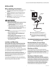
After the controller is installed, wired, and set, it should be
tested with the system in operation. First, allow the system to
stabilize. Then, observe the operation of the controller while
raising and lowering its setpoint. Pressure should increase
when the setpoint is raised and decrease when the setpoint is
lowered. Use accurate pressure testing equipment when
checking out the controller. Do not rely on inexpensive gauges.
The controllers are carefully calibrated at the factory.
Make sure the modulating motor or modulating valve actuator
reaches the low- and high-fire positions at the proper points. If
the motor or actuator runs in the proper direction when the
setpoint is adjusted, assume that the controller is operating
properly. If it runs in the wrong direction, reverse the B and W
wires. Observe the action of the motor or actuator until it
stabilizes. If the motor or valve is moving constantly, widen the
proportioning range (not adjustable on an L91A) incrementally
until the system is stable.
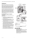
If a Controller Seems to Operate
Improperly
If the controller is suspected of operating improperly, it may be
further checked by:
1. Leaving the controller installed where it is, but discon-
necting all power to the controller motor or valve.
2. Loosening the cover screw below the main scaleplate
and removing the cover.
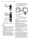
3. Disconnecting the wires from the controller.
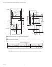
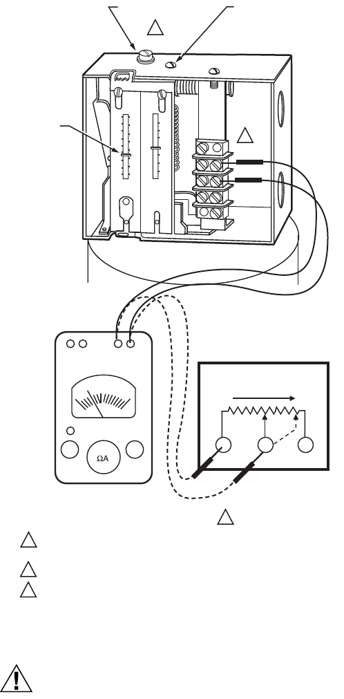
4. Connecting an ohmmeter between controller terminals B
and W to measure the resistance for the potentiometer in
the controller. The ohmmeter should read about 135
ohms for an L91A,B, or D.
5. Connecting the ohmmeter between controller terminals
W and R (Fig. 8) and raising the setpoint of the controller
above the actual pressure being measured. The ohmme-
ter should read the full value of the potentiometer mea-
sured in step 4 (135 ohms for an L91A,B, or D).
6. Slowly lowering the setpoint of the controller while
observing the ohmmeter reading. The resistance should
drop to zero at some setpoint below the actual pressure.
7. Making an approximation of the proportioning range by
observing the change in setpoint required for a resis-
tance change from zero to full value.
8. When the controller is operating properly, reconnecting
the wires, replacing the cover, tightening the cover
screw, and resetting the controller to the desired value.
9. Reconnecting power to the controlled motor or valve.
Fig. 7. Checking L91 Proportioning Pressuretrol
®
Controller.
CAUTION
Equipment Damage Hazard.
Failure to follow checkout instructions can damage
components or systems.
Do not put the system into service until you have
satisfactorily completed all applicable tests described in
this Checkout section, all tests in the Checkout section
of the applicable instructions, all tests for the flame
safeguard control, and any tests required by the burner
and boiler manufacturers.
DIFF.
MAIN
MIN
B
D
F
E
C
A
0
4
6
2
1
3
4
5
16
14
12
10
8
0
kPa
OZS
IN
2
DIFF. IS
ADDITIVE
2
6
7
M8546A
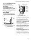
PROPOTIONING
RANGE ADJUSTING
SCREW
(L91B,D ONLY)
INPUT
OUTPUT
ZERO
ADJ
0
135
W
W
R
R
B
B
SETPOINT
INCREASE
MAIN SCALE
ADJUSTING SCREW
MAIN SCALE
SETTING
INDICATOR
INCREASES TO
135 OHMS
OHMMETER
1 KNURLED ADJUSTMENT KNOB ON 10 TO 300 PSI [0.07 TO 2.07 MPA]
MODELS.
2 TERMINALS ARE LABELED
3 135 OHMS ON L91A,B OR D.
3
2
1