


L91A,B,D PROPORTIONING PRESSURETROL
®
CONTROLLERS
60-2152—08 6
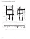
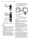
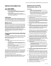
Fig. 3. L91 terminal blocks and internal schematics.
WIRING
1. Disconnect power supply before beginning installation to
prevent electric shock and equipment damage. All wiring
must comply with applicable electrical codes,
ordinances, and regulations. Use NEC Class 1 (line
voltage) wiring.
2. For normal installation, use moisture-resistant No. 14
wire suitable for at least 167°F (75°C) if you are using
the controller with a flame safeguard primary control, or
at least 194°F (90°C) if you are using it with a program-
ming control.
3. For high temperature installations, use moisture-
resistant No. 14 wire, selected for a temperature rating
above the maximum operating temperature.
4. Disconnect the power supply before beginning wiring to
prevent electrical shock and equipment damage.
5. All models have a terminal block inside the cover (Fig. 3)
and two 7/8 in. (22.2 mm) holes in one side for 1/2 in.
conduit, cable, or wires. Remove the front cover by loos-
ening the screw at the bottom of the scaleplate.
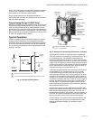
6. Refer to Fig. 4 for typical hookup. W and B connections
may be interchanged at the motor for reverse action
(cooling). Follow the burner or boiler manufacturer’s
wiring diagram if provided. Also refer to the wiring
diagrams in the motor instructions.
7. Replace the front cover when wiring is completed.
Fig. 4. Hookup of L91 Proportioning Pressuretrol
®
Controller to Series 90 Modulating Motor.
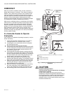
Setting
In all models, the proportioning range (also called throttling
range) extends above the main scale setpoint (Fig. 5). The
proportioning range is fixed on L91A models, but is adjustable
on L91B,D models. (For values, refer to Table 1 in the
Specifications section.)
Main Scale Set Point (All models)
Adjust the main scale setpoint for the desired operating
pressure by turning the main scale adjusting screw (Fig. 7) or
knurled adjustment knob on 10 to 300 psi (0.07 to 2.07 MPa)
models, on the top of the case, until the main scale setting
indicator is at the minimum pressure desired. The
proportioning range extends above this value. The scaleplate
is marked in both customary (oz/sq in., psi, or in. Hg) and
metric (kPa, MPa, or mm Hg) units.
Use of L91 Proportioning Controller with
Limit Controllers
The L91 main scale setpoint plus the value of the differential
(proportioning range) must be less than or equal to the limit
controller’s (L404) main scale setpoint.
For example, to control system pressure between 70 and 80
psi: select an L91B, 5-150 psi operating range, adjustable
differential (proportioning, throttling range) of 5 to 23 psi and an
L404A, 10-150 psi, adjustable differential of 8 to 16 psi. Set the
L404A main scale setpoint at 80 psi and its adjustable
differential at 10 psi. The L404A settings will then provide boiler
pressure limit control between 70 and 80 psi. An L91B
differential (proportioning range) pressure of 5 psi is desired.
Therefore, an L91B main scale setpoint of between 70 and 75
psi is required (L91 main scale setpoint plus its differential
must be less than or equal to the limit controller main scale set
M8522A
L91A,B
R
W
B
ACTION ON
PRESSURE FALL
WB
1
L91D
R
W
B
R
W
B
ACTION ON
PRESSURE FALL
WB
1
1
ACTION ON
PRESSURE FALL
W
B
TERMINALS ARE LABELED.
FRONT POTENTIOMETER
REAR POTENTIOMETER
M8520A
(HOT) L1 L2
3
1
2
3
2
1
R
W
B
W1
R1
B1
T1
T2
L91 PROPORTIONING
CONTROLLER
SERIES 90
MODULATING MOTOR
CLOSED
(LOW FIRE)
OPEN
(HIGH FIRE)
M9484
M9494
TRANSFORMER
WIPER MOVES TOWARD W END OF
POTENTIOMETER ON PRESSURE RISE,
AND TOWARD B END ON
PRESSURE FALL.
TERMINALS ARE LABELED.
POWER SUPPLY. PROVIDE DISCONNECT MEANS AND
OVERLOAD PROTECTION AS REQUIRED.