


LYNXR-I Installation and Setup Guide
- 9 -
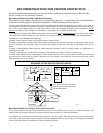
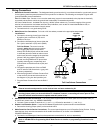
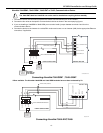
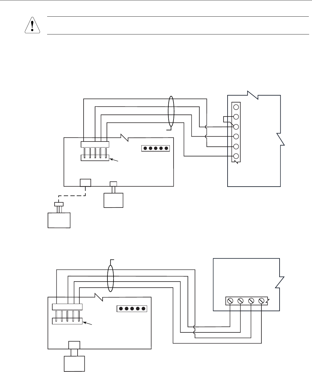
AlarmNet 7845GSM*, 7845i-GSM*, 7845i-ENT or 7845i, Communications Device
The 7845i-ENT/7845i and 7845CV2 can not be used for installations requiring 24-hour standby.
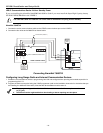
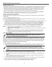
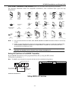
1. Connect the 4-wire communications cable to the LRR/IP Communications port on the LYNXR-I.
2. Connect the four wires to the specific Communications device as shown in the accompanying figures.
3. If you are installing a 7845GSM or 7845i-GSM you must also install a jumper between terminals 2 and 3 on the
communications device.
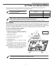
4. Connect the device to the Internet via a cable/DSL modem and router or to an Intranet (LAN) via the appropriate Ethernet
connection, if applicable.
7845GSM / 7845i-GSM
LYNX
SUPER HIGH
CAPACITY
BATTERY
(OPTIONAL)
REQUIRED FOR
24-HR BACKUP
7845i-GSM-010-V0
GND
Z3 OR DATA OUT
Z1/Z2 OR DATA IN
ECP (+) VOLTAGE INPUT
RED
BLK
GRN
YEL
RED
BLK
GRN
YEL
4
5
6
3
5
4
4-WIRE CABLE (N4632-4)
1
2
TB1
LRR/IP COMMUNICATIONS PORT
LYNXR-I CONTROL PANEL
NC
+12 VDC
GND
DATA IN
DATA OUT
LYNX
STANDARD
CAPACITY
BATTERY
Connecting AlarmNet 7845GSM* / 7845i-GSM*
* When available. The AlarmNet 7845GSM and 7845i-GSM modules have not been evaluated by UL.
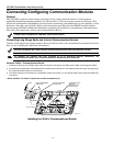
7845i-ENT / 7845i
07000-013-V2
GND
DATA IN
DATA OUT
(+) VOLTAGE INPUT
RED
BLK
GRN
YEL
RED
BLK
GRN
YEL
TB 1
LYNXR-I CONTROL PANEL
NC
RED
BLK
GRN
YEL
+12 VDC
GND
DATA IN
DATA OUT
4-WIRE CABLE (N4632-4)
LYNX
STANDARD
CAPACITY
BATTERY
LRR/IP COMMUNICATIONS PORT
Connecting AlarmNet 7845i-ENT/7845i