


2
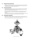
2.1 Reagent Head Assembly
The typical reagent head assembly consists of reagent head, diaphragm, and suction and discharge
cartridge check valves. This assembly is the only part of the pump to contact the process liquid;
consequently, maintenance is critical to pump performance.
2.2 Control Assembly
The OMNI
®
pump incorporates a lost motion style of stroke length adjustment to limit diaphragm
travel during the suction portion of each stroke. The stroke length setting is indicated by a (0% –
100%) scale located on the stroke adjustment assembly.
Stroke length is changed by loosening the locking screw and turning the hand knob. This turns a
mechanism, which limits rearward travel of the diaphragm. Refer to Section 6.2 for further
information.
For automatic flow rate control, users can consider the Pulsafeeder MPC speed based control system,
please contact your local Pulsafeeder dealer or representative for more information.
2.3 Gear Ratio Assembly
OMNI
®
pumps are driven by an electric motor mounted on the motor adaptor input flange. The
motor drives a set of worm gears that convert rotational speed into torque. They, in turn, power the
eccentric shaft assembly that converts rotary motion into reciprocating motion.
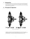
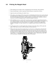
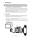
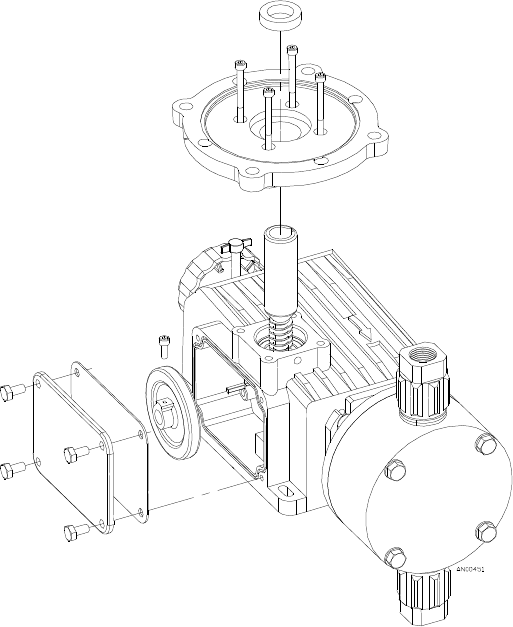
Figure 2, isometric view