16
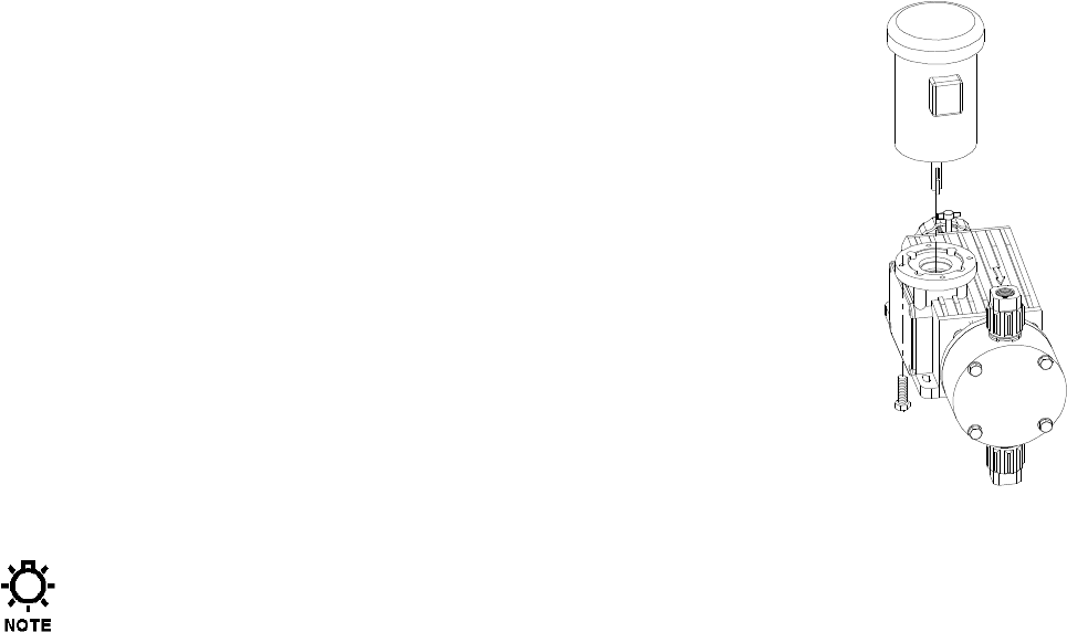
7.4 Motor Removal & Reinstallation
1. Disconnect the power source to the drive motor.
2. Disconnect the motor wiring from the motor.
3. Remove the four bolts retaining the motor to the motor adaptor.
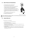
The motor shaft fits into a bore on the pump input shaft.
4. Slide the motor shaft out of the pump input shaft.
Be careful not to lift the pump input shaft up out of the pump.
5. Apply a lubricant such as Loctite™ Silver Grade® Anti-seize paste
(or similar) to the motor shaft and key before reassembling..
6. Reinstall the motor by sliding the motor shaft into the pump input
shaft.
7. Insert and tighten the four bolts removed in step 3.
8. Reconnect the motor wiring to the motor.
9. Connect power to the drive motor.
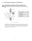
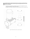
Figure 13, motor mounting
Motor rotation must be wired for CW rotation, as viewed from the top of the motor, as noted by the
arrow on the top of the pump housing.
7.5 Gearset Removal
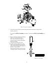
Gearset diagram is on following page
1. Disconnect power source and wiring from the motor.
2. Set stroke adjustment to zero.
3. Remove motor from the pump (refer to Section 7.4).
4. Remove the four socket head screws (Item 1) that attach the motor adaptor (Item 2) to the
pump housing and remove the adaptor.
5. Loosen and remove the Hex Head Bolts (Item 5), and remove the pump side cover (Item 6)
and gasket (Item 7).
6. Remove the Worm Shaft Assembly (item 4) by carefully pulling it straight up out of the
pump housing. On DC2 and DC3 models, be careful not to lose the lower thrust bearing
and washers (items 11 and 12).


