


14
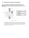
7.3.2 Check Valve Removal & Reinstallation, Cartridge type
Valving that is of the cartridge design is intended to be replaced as an assembly.
15. Disconnect the power source to the drive motor.
16. Relieve all pressure from the piping system.
17. Take all precautions necessary to prevent contamination to the environment and personnel exposure
to hazardous materials.
18. Close the inlet and outlet shutoff valves.
19. Disconnect the suction piping at the installed union near the suction port.
20. Loosen and remove the suction valve cartridge slowly to drain any liquid from the reagent head.
21. Disconnect the discharge piping at the installed union near the discharge port.
22. Loosen and remove the discharge valve cartridge slowly to drain any trapped liquid.
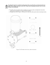
23. Reinstall both new valve assemblies, taking care to ensure that they are in the correct ports.
Lettering on the side of each valve should be right side up when assembled to the pump. Each valve
assembly should also have an arrow, which should indicate direction of flow (upwards). Do not coat
the threads of the cartridge vale with a pipe sealant. Each valve cartridge should be tightened only
until the o-ring seal makes good contact with the reagent head surface. Over-tightening will cause
damage and lead to leaks
24. Reinstall both suction and discharge piping. Secure the cartridge while making your external
connections to prevent rotating the cartridge and over-tightening it into the pump.
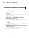
7.3.3 Check Valve Removal & Reinstallation, Tie-bar type
1. Disconnect the power source to the drive motor.
2. Relieve all pressure from the piping system.
3. Take all precautions necessary to prevent contamination to the environment and personnel exposure
to hazardous materials.
4. Close the inlet and outlet shutoff valves.
5. Loosen the suction valve tie-bar bolts (4) and spring the suction piping slightly away from the head,
allowing liquid to drain. It may be necessary to loosen a union or flange.
6. Remove the suction check valve assembly by sliding it towards you, holding it together as a unit.
Note carefully the position of the component parts, to assist in re-assembly.
7. Loosen the discharge valve tie-bar bolts (4) and spring the discharge piping slightly away from the
head, allowing liquid to drain. It may be necessary to loosen a union or flange.
8. Remove the discharge check valve assembly by sliding it towards you, holding it together as a unit.
Note carefully the position of the component parts, to assist in re-assembly.
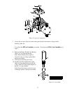
9. Disassemble both valves and check components for wear or damage. The seats should have a sharp
edge and be free from dents or nicks. Hold a ball firmly against the seat in front of a bright light and
inspect for fit, observation of light between the ball and seat is cause for replacement.
10. Reassemble both valves using new parts as required. Sealing o-rings should always be replaced.
11. Replace both valve assemblies onto the pump, taking care to ensure they are oriented correctly, with
the balls above the seats, and the seats oriented with the sharp edge up and the chamfered edge down.