


6
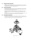
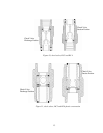
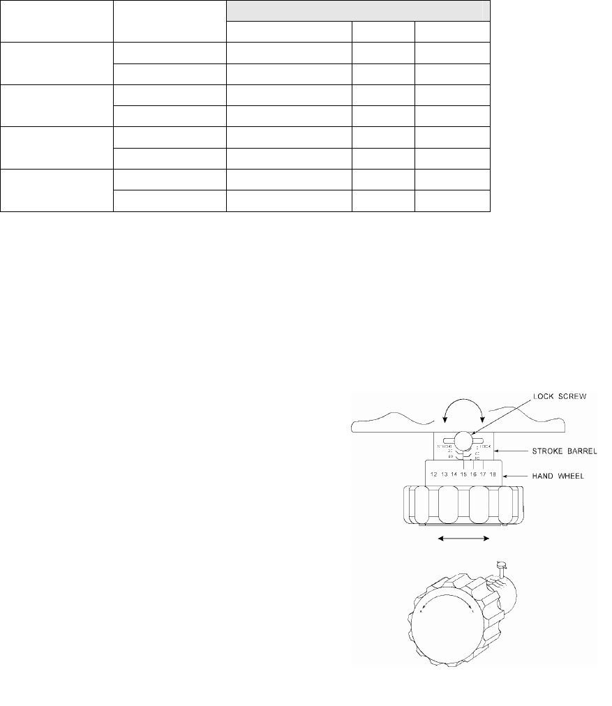
Figure 4, stroke adjustment
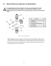
6. Equipment Startup
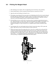
6.1 Fastener Inspection
All pump fasteners should be checked prior to pump operation, and occasionally during use. This
would include reagent head mounting bolts, motor mounting bolts, and the hardware that secures the
pump to its foundation. Most hardware can be checked simply to ensure it is not loose. However, utilize
the following values when checking reagent head bolt torque:
Reagent Head Bolt Torque
Model Material
# Bolts and size N-m In. - Lbs
Plastic (4) M6 * 1.0 3.39 30
DC2
Metal (4) M6 * 1.0 3.39 30
Plastic (4) M8 * 1.25 6.77 60
DC3 and 4
Metal (4) M8 * 1.25 6.77 60
Plastic (6) M8 * 1.25 8.46 75
DC5
Metal (6) M8 * 1.25 8.46 75
Plastic (6) M8 * 1.25 8.46 75
DC6
Metal (6) M8 * 1.25 8.46 75
6.2 Output Adjustment
All OMNI
®
pumps have a hand wheel for manual stroke adjustment. The hand wheel can be adjusted to
any point from 0 to 100%. This value represents the stroke length setting and therefore the flow rate of
the pump relative to its maximum output.
1. Turn the red lock screw counterclockwise to release the
stroke lock. Making adjustments without releasing the
lock may damage the mechanism.
2. Adjust the hand wheel to the desired output.
a) The stroke barrel indicates stroke length in 20%
increments.
b) The hand wheel indicates stroke length in 1%
increments.
For example, to set the pump to 75% stroke length,
(starting from the factory default setting of 0%) turn the
hand wheel counter clockwise until he 60% indicator is
visible on the stroke barrel.
Continue the counter clockwise rotation until the hand
wheel indicator is at 15. Refer to Figure 4.
3. Turn the lock screw clockwise to lock the stroke adjustment
into position.
Adjustments can be made while the pump is at rest or
operating, although adjustments are easier to make
while the pump is in operation.