


69-1199—28
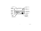
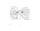
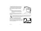
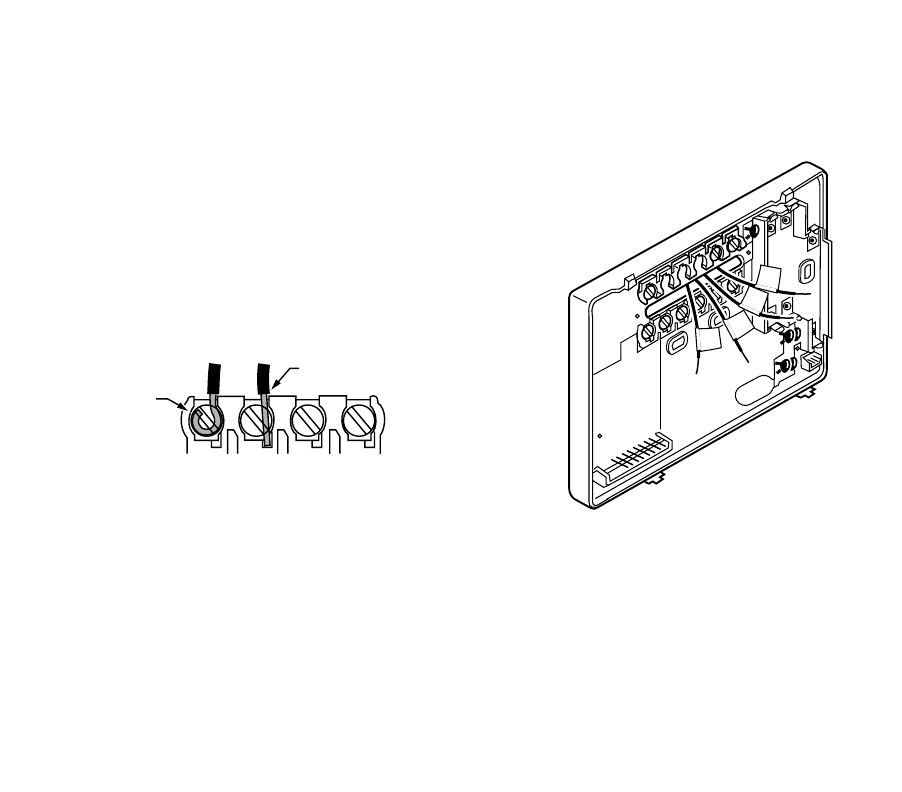
STEP 4. WIRE WALLPLATE TERMINALS
IMPORTANT
All wiring must comply with local codes and ordinances. If unsure about household wiring procedures, call
your local heating/air-conditioning contractor.
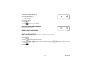
Refer to the labels
y
ou placed on the wires when
y
ou removed the
old thermostat (see illustration).
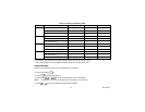
❑ Match the letter of
y
our old thermostat wire with the
correspondin
g
terminal letter on
y
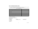
our new thermostat. Refer to
Table 2.
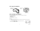
❑ Remove the factor
y
-installed jumper connectin
g
terminals R and
RC if wires are connected to both of those terminals.
❑ For wirin
g
dia
g
rams, if needed, see pp 21-22.
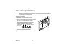
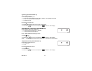
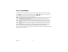
❑ Loosen the terminal screws. Slip each wire beneath its matchin
g
terminal. Wraparound and strai
g
ht connections are both
acceptable, (see illustration). Ti
g
hten the terminals.
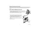
❑ Plu
g
the hole in the wall with insulation to help prevent drafts
from adversel
y
affectin
g
thermostat operation.
M16425
R
W
Y
G
M4826
FOR WRAPAROUND
INSERTION STRIP
7/16 IN. (11 MM).
FOR STRAIGHT INSERTION
STRIP 5/16 IN. (8 MM).