


69-1641EF G.R. 09-02 Printed in China www.honeywell.com
Automation and Control Solutions
Honeywell Honeywell Limited-Honeywell Limitée
1985 Douglas Drive North 35 Dynamic Drive
Golden Valley, MN 55422 Scarborough, Ontario
M1V 4Z9
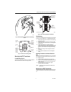
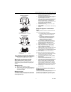
WIRING
1. Disconnect power supply before installing
transformer. All wiring must comply with local
electrical codes and ordinances. Tape all unused
exposed leadwires separately.
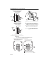
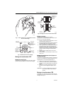
2. Connect primary leadwires to line voltage power
supply. See Fig. 23 through 25.
3. Connect transformer secondary leadwires to 24
Vac control system.
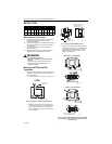
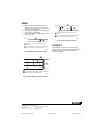
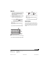
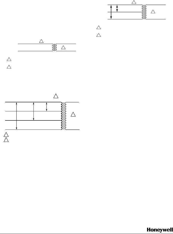
Fig. 10. AT20/AT40 Transformer schematic.
Fig. 11. AT72D, AT87A Transformer schematic.
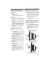
Fig. 12. AT88 Transformer schematic.
CHECKOUT
After installation is complete, turn on power supply.
Placed controlled equipment into operation and observe
through at least one complete cycle. Make sure it
functions as intended.
SECONDARY CONNECTIONS ARE BLUE AND YELLOW
LEADWIRES.
BLACK IS COMMON WITH RESPECT TO THE TRANSFORMER
WINDING ONLY AND NOT THE EXTERNAL CIRCUIT.
WHITE (120V) OR ORANGE (240V)
C
OMMON
1 24 VAC
2
BLACK
1
2
M2066
0
1
1 SECONDARY CONNECTIONS ARE SCREW TERMINALS.
2 BLACK IS COMMON WITH RESPECT TO THE TRANSFORMER
WINDING AND NOT THE EXTERNAL CIRCUIT.
2
120 VAC
WHITE
208 VAC
240 VAC
BLACK
RED
ORANGE
24 VAC
M18321
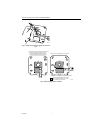
SECONDARY CONNECTIONS ARE BLUE AND YELLOW
LEADWIRES.
BLACK IS COMMON WITH RESPECT TO THE TRANSFORMER
WINDING ONLY AND NOT THE EXTERNAL CIRCUIT.
ORANGE
RED
1
2
M2066
1
C
OMMON
1 24 VAC
2
BLACK
208 VAC
240 VAC