


AT20, AT40, AT72D, AT87, AT88 AT TRANSFORMERS
69-1641EF 2
INSTALLATION
When Installing This Product…
1. Read these instructions carefully. Failure to follow
them could damage the product or cause a
hazardous condition.
2. Check the ratings given in the instructions and on
the product to make sure the product is suitable for
your application.
3. The installer must be a trained, experienced
service technician.
4. After installation is complete, check out product
operation as provided in these instructions.
WARNING
Electrical Shock Hazard.
Can cause severe injury, death or property
damage.
Disconnect power supply before beginning
installation to prevent electrical shock or
equipment damage.
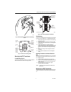
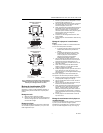
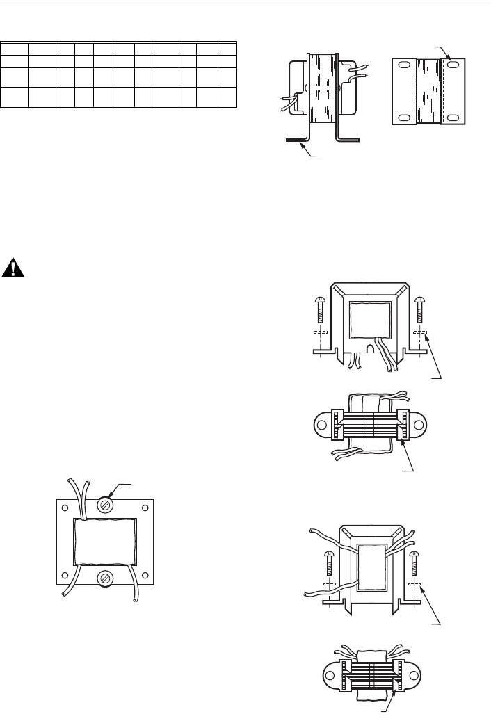
Mounting the AT20A and AT40A
Transformer
1. Mount the transformer to best suit the replacement
application. The transformer may be mounted in
one of three ways:
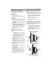
a. Use bolts in slots for direct mounting (Fig. 6).
Fig. 1. Use bolts in slots for panel mounting.
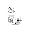
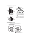
b. Horizontal channel frame. Place frame over
laminations as shown in Fig. 7 and bend tabs
over to hold transformer securely in place.
Mount transformer over 3/16 in. (5 mm) holes
in mounting feet.
Fig. 2. Foot mounting (AT20C shown).
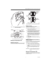
c. Vertical channel mounting. Place frame over
laminations as shown in Fig. 8 and bend tabs
over to hold transformer securely in place.
Mount transformer through 3/16 in. (5 mm)
holes in mounting feet.
Fig. 3. Use horizontal channel frame for horizontal
foot mounting; vertical channel frame for vertical
foot mounting.
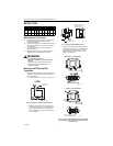
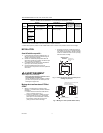
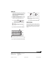
ABCDE
in. mm in. mm in. mm in. mm in. mm
AT40C 2-
13/32
61 7/8 22 1-3/4 44 2-3/16 56 2-7/8 73
AT87A 2-
13/32
61 1 25 1-3/4 44 2-1/16 52 3 76
USE WASHER
S
IF NECESSAR
Y
PANEL
MOUNTING
M2065
4
M2065
5
USE SCREWS OR BOLTS
THROUGH SLOTS (4) IN
MOUNTING FEET
MOUNTING FOOT (2)
VERTICAL FOOT MOUNTING
M2065
7
B
END OVER TABS (4) TO
S
ECURE TRANSFORMER
USE WASHERS
IF NECESSARY
M2066
5
H
ORIZONTAL FOOT MOUNTING
BEND OVER TABS (4) TO
SECURE TRANSFORMER
USE WASHERS IF NECESSARY