


AQUATROL ZONE SYNCHRONIZING BOILER RESET CONTROLS
69-1979—04 2
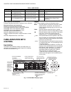
Table 1. AQ251 Models
AQ251 Approvals and Standards:
Canadian Standards Association: Certified, File No. LR76030
Replacement Parts and Accessories:
AQ1000: non-programmable zone thermostat
AQ15100B: Replacement Boiler Reset Control Module
AQ15740B: 4-zone valve expansion module
AQ15540B: 4-zone pump expansion module
AQ10X38: 24 Vac 38 VA transformer
AQ12C10: Replacement sensor, outdoor
AQ12C11: Replacement sensor, supply and return on boiler
loop
AQ12C20: Replacement floor / slab sensor
FAMILIARIZATION WITH
CONTROL
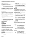
User Interface
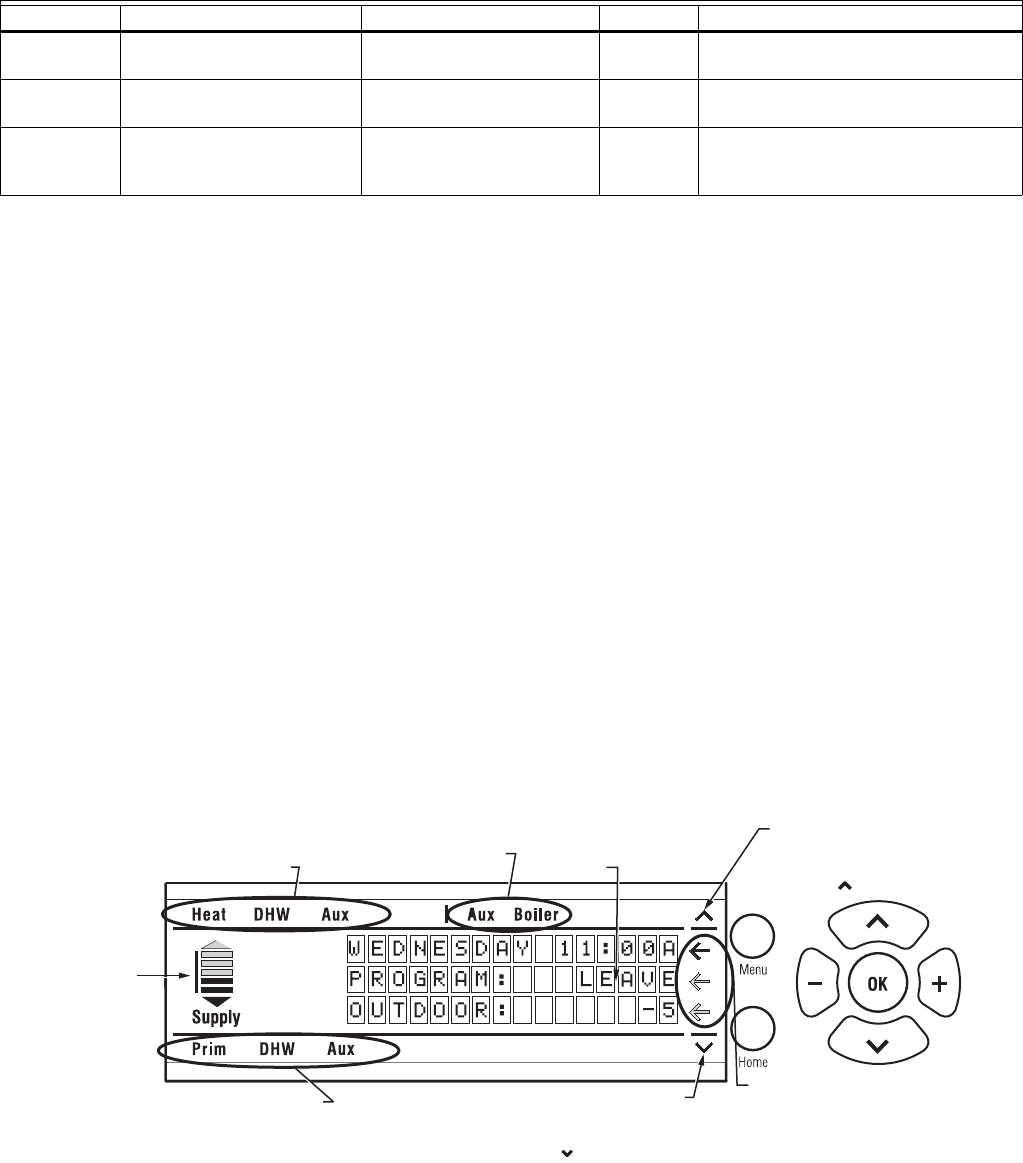
The AQ251 User Interface consists of an LCD screen (16
characters by 3 rows) and a 7 button keypad for navigating
the menus as illustrated in Fig. 1.
Keypad
The 7- button keypad provides the following functions.
Menu Press this button to access the User Menu. When
pressed while in a sub-menu, the sub-menu’s
values are saved before going up one level in the
current menu.
Home Press this button to leave the User or Installer
Menu and return to the Home Page display screen.
OK Press this button to enter a sub-menu of the active
menu item. A menu item is active when the
indicator arrow (←) is positioned beside the item.
^
and v Press these buttons to scroll up/down in the menu
items. Pressing one of these buttons automatically
exits the edit mode, and the selection moves to the
previous or next menu item.
– and + Press these buttons to decrease/increase the value
of a selected menu item, or to scroll through a list of
pre-defined options.
- If the menu item being modified is a number, the
displayed value will decrease/increase by pressing
these buttons. When holding the – or + button for
more than a second, the values automatically
decrease/increase at a faster pace, similar to
setting the time on a digital clock radio
.
- If the menu item is an option, pressing these
buttons scrolls through the list of available options
one at a time.
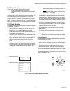
Fig. 1. LCD Dot Matrix Display Layout.
Model Function DHW Zones Zone Control
AQ25142B Reset Boiler Control Panel
with integrated zoning
Selectable DHW priority, with
optional priority override
2 – 16,
in sets of 4
Line voltage circulators or 2-wire zone
valves
AQ25144B Reset Boiler Control Panel
with integrated zoning
Selectable DHW priority, with
optional priority override
2 – 16,
in sets of 4
24 Vac zone valves with end switches
AQ25110B Reset Boiler Control Panel
with no integrated zoning
Selectable DHW priority, with
optional priority override
1 None; user can add zoning with
Expansion Zoning Panels (sold
separately)
ARROW INDICATES
THE CURRENTLY SELECTED
“ACTIVE” MENU ITEM.
M27748
UP ARROW, IF DISPLAYED,
INDICATES THAT OTHER MENU
ITEMS EXIST ABOVE AND CAN
BE VIEWED BY SCROLLING
UP WITH THE BUTTON.
DOWN ARROW, IF DISPLAYED,
INDICATES THAT OTHER MENU ITEMS
EXIST BELOW AND CAN BE VIEWED
BY SCROLLING DOWN WITH
THE BUTTON.
STATUS OF SYSTEM DEMANDS
- CALL FOR HEAT
- CALL FOR DHW
- SIGNAL ON AUXILIARY INPUT
STATUS OF SYSTEM OUTPUTS
- AUXILIARY OUTPUT ACTIVE
- BOILER T-T OUTPUT ACTIVE
DISPLAY AREA SHOWING
SYSTEM STATUS AND MENU
OPTIONS AND SELECTIONS
MADE
STATUS OF LINE VOLTAGE OUTPUTS
- PRIMARY (BOILER) HEAT
- DHW PUMP
- AUXILIARY “PUMP” OUTPUT
GRAPHIC SHOWING
THE PERCENTAGE
OF THE BOILER’S
HEATING CAPACITY
A
T WHICH IT’S
OPERATING; ARROWS
A
BOVE AND BELOW
THE BAR SHOW THE
TREND OF THE
BOILER’S
TEMPERATURE
(UP OR DOWN)