USER OPERATION AND MAINTENANCE
69-1979-04
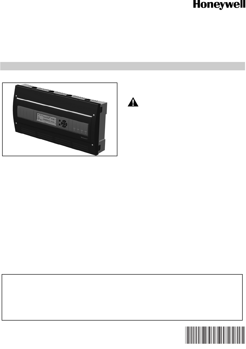
AQUATROL Zone Synchronizing
Boiler Reset Controls
AQ251
APPLICATION
The AQ251 series of AQUATROL® Boiler Reset Controls
provides simplified, energy-efficient outdoor temperature
compensated control of single-temperature, residential
hydronic heating systems. The AQ251 easily converts a single
zone heating system into a room-by-room comfort control
system, or upgrades a basic, relay-logic zoning system to
intelligent “Zone of Greatest Demand” control with outdoor
reset for increased energy efficiency and with reduced boiler
cycling.
AQ251 boiler controls can ensure ample supply of hot water
for both space heating and priority generation of domestic hot
water for bathing, dishes and laundry.
When AQ1000 communicating thermostats are used with the
AQ251 Zoning Modules, they can use the same wiring as
existing thermostats. Night setback operation can be
programmed from the AQ251 panel. Thanks to the network
communication capability of the AQ251 controls, AQ1000
thermostats in the home can display the actual outdoor
temperature when an outdoor sensor is connected to the
AQ251 Control Panel.
WARNING
Only trained, experienced, licensed service
technicians should service this Control Panel. The
front cover of the AQ251 Control Panel should not
be removed, as this will expose the user to
potentially dangerous line voltage (120V)
electricity.
Congratulations!
The AQUATROL AQ251 installed on your heating system is
the most powerful, yet user-friendly hydronic heating control
system available on the market for residential and light
commercial installations.
This instruction sheet contains all the information you need to
program the comfort settings of the AQ251 and to customize
its operation for your home or business. For detailed
information on the operation of this control, please consult the
trained hydronic heating professional that installed the AQ251
control.
CONTENTS
Application ........................................................................ 1
Familiarization with Control .............................................. 2
User Interface .................................................................. 2
LCD Display Panel Layout ................................................ 3
Programming Instructions ................................................. 4
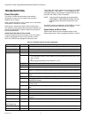
Troubleshooting ................................................................ 6
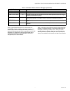
System Status and Error Codes ....................................... 6
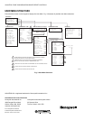
User Menu Structure ......................................................... 8
This AQUATROL AQ251 Control Panel was installed by a trained hydronic heating contractor.
To service this product, or for any questions relating to its installation, please contact:
Installing contractor: ________________________________________________________
Address: __________________________________________________________________
Phone: (_______) __________________________________________________________


