


2 Installation continued
B Wiring
Relay Wiring:
All three relays have Form C, dry contacts. Any
required power source must be within the 3 amp
rating and fused or current limited to keep from
damaging the contacts.
Electrical wiring must comply with all applicable
codes. Plant equipment that may be involved and
operating conditions should be discussed with local
operating personnel to determine if any special
needs should be taken into account.
• Relay wiring must be run in separate conduit
from the sensor cable if the relay circuit is AC.
Nearly all start-up problems are due to improper
wiring or monitor configuration. Please follow these
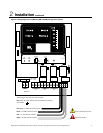
guidelines carefully. Figure 2 presents a wiring
diagram for the Manning GM-1.
Sensor Wiring:
• See sensor manual for proper sensor cable.
• See sensor manual for proper sensor location.
AC Power Wiring:
• Never run AC circuits in the same conduit as
the sensor cable.
• Use only stranded cable for AC power,
relay outputs, and sensor input cables.
Note: Relays are energized in a non-alarmed
condition so that a power loss in the Manning GM-
1 will result in an alarm.
• The units must have a proper third wire
ground for safety and sensor shielding.
Be sure to follow local codes.
• All AC cables must be kept away from the
incoming sensor cables, i.e., do not put AC
cables inside conduit containing sensor
cables.
• Keep all wiring away from variable speed
drives and SCR control units to minimize
electrical noise exposure.
• Electrical Power: 120 VAC, 50/60 Hz, 0.35
amps.
• Electrical power ground: The unit must be
properly grounded.
Risk of electric shock.
Manning GM-1 Gas Monitoring Alarm System 19546 GM1 07/09 REVD Copyright © 2009 Honeywell Analytics. All Rights Reserved. 8