


3 Operation continued
G Maintenance
The Manning GM-1 is designed for long life and high
reliability. Honeywell Analytics recommends
checking signal voltages monthly and logging them
on the data sheet included with your Manning GM-1.
Additionally, the sensor being monitored should be
exposed to the target gas on a monthly basis while
all alarm functions are verified at the Manning GM-1.
This will test the sensor and any equipment con-
nected to the relays in addition to the Manning GM-1.
H Replacement Parts
For replacement parts, contact Honeywell Analytics.
Be sure to give serial number and model number of
unit.
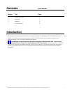
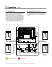
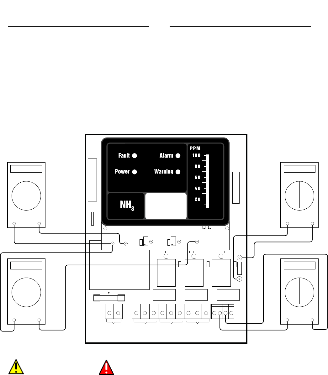
Figure 4: Troubleshooting the Manning GM-1 Gas Monitoring Alarm System
NO NCC NO NCC NO NCCLN
WARNING
RELAY*
120 VAC
WARNING
RELAY
WARNING
ADJUST
ALARM
ADJUST
TP
WARNING
TP
ALARM
TP
SIG
BOT TOP
TP
GND
TP
+20V
MODEL G/M
MAINBOARD REV D
C11
16
7
ALARM
RELAY
FAULT
RELAY
TP CURRENT DRAW
ALARM
RELAY*
FAULT
RELAY*
+ + +
SHLD GND
+
24 SIG
FUSE RATING
250V 1.0 AMP
+20V
Black
-
Red
+
VDC
SENSOR DEPENDENT
Black
-
Red
+
mVDC
+24V
Black
-
Red
+
VDC
0.4 - 2.0 V
Black
-
Red
+
VDC
Signal from sensor
Display power
supply voltage
AC fuse
Sensor current draw
(1mV per 10 mA)
Power supply
voltage to sensor
Risk of electrical shock.
Potential hazard.
Manning GM-1 Gas Monitoring Alarm System 19546 GM1 07/09 REVD Copyright © 2009 Honeywell Analytics. All Rights Reserved. 12