


3 Operation
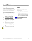
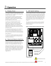
A Display Panel C DIP Switch Setting
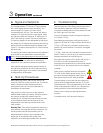
A 20-segment Bargraph Display indicates the gas
concentration level. The bottom LED is always lit to
indicate power to the display.
The two position DIP switch in the center of the bottom
board controls the latching of the alarm light and alarm
relay. Switch 1 (left) controls the alarm relay. Switch 2
(right) controls the alarm light. Putting the switch in the
on (up) position will latch the corresponding function.
Putting the switch in the off (down) position will cause
the corresponding function to be not latched (see
Figure 3).
The Warning LED indicates the warning level as
determined by the warning setpoint has been
exceeded. The Warning LED and Warning Relay
operate together and never latch.
The Alarm LED indicates the alarm level as
determined by the alarm setpoint has been
exceeded. The Alarm LED and Alarm Relay are
independently latchable or non-latchable as
determined by the DIP switch on the main board.
Standard factory settings are to latch the LED and
not latch the relay.
This allows the alarm condition to remain activated if
desired even if the gas concentration goes back to
below the setpoint.
Figure 3: Warning adjustment and DIP switch settings
Manning GM-1 Gas Monitoring Alarm System 19546 GM1 07/09 REVD Copyright © 2009 Honeywell Analytics. All Rights Reserved. 10
The Power LED indicates power to the monitoring
unit. This LED will flash during the one minute
power up delay indicating that all relays are held in
the normal condition to allow for sensor stabilization
during power up.
The Fault LED indicates a signal input of less than
1.4 mA (0.14 volts) at TP Sig. The Fault LED and
Fault Relay always latch.
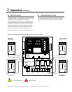
B
Reset and Silence Switches
Pushing the Reset switch will reset the fault light,
fault relay, alarm light, and alarm relay. If either
condition still exists, the appropriate light and relay
will return to its tripped state after a time delay.
Pushing the Silence switch will silence the horn on
the bottom of the Manning GM-1 until the next event
occurs. The horn is triggered by a fault or an alarm
condition. The horn will clear itself if the alarm and
fault relay clear. A warning condition does not
trigger the horn.
NO NCC NO NCC NO NCCLN
WARNING
RELAY*
120 VAC
WARNING
RELAY
WARNING
ADJUST
ALARM
ADJUST
TP
WARNING
TP
ALARM
TP
SIG
AA
SW1
BOT TOP
TP
GND
TP
+20V
MODEL G/M
MAINBOARD REV D
C11
16
7
ALARM
RELAY
FAULT
RELAY
TP CURRENT DRAW
ALARM
RELAY*
FAU LT
RELAY*
+ + +
SHLDGND
+
24 SIG
FUSE RATING
250V 1.0 AMP
1 2
0.4 - 2.0 V
Black
-
Red
+
VDC
Warning adjust pot
DIP switches on
bottom of board
Do Not Adjust!
Factory set pots
Risk of electrical shock.
Potential hazard.