


308350 7
Installation
General Information
NOTE: Reference numbers and letters in parentheses
in the text refer to the callouts in the figures and the
parts drawing.
NOTE: Always use Genuine Graco Parts and Acces-
sories, available from your Graco distributor. Refer to
Product Data Sheet, Form No. 305724. If you supply
your own accessories, be sure they are adequately
sized and pressure rated for your system.
Grounding
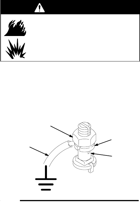
WARNING
FIRE AND EXPLOSION HAZARD
Before operating the pump, ground the
system as explained below. Also read
the section FIRE AND EXPLOSION
HAZARD on page 5.
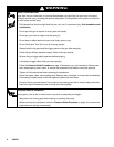
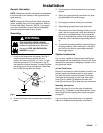
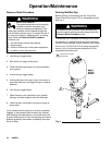
1. Pump: use a ground wire and clamp. See Fig. 1.
Loosen the grounding lug locknut (W) and
washer (X). Insert one end of a 1.5 mm@ (12 ga)
minimum ground wire (Y) into the slot in lug (Z)
and tighten the locknut securely. Connect the other
end of the wire to a true earth ground. Order Part
No. 237569 Ground Wire and Clamp.
Fig. 1
W
X
Y
Z
0864
2. Air and fluid hoses: use only electrically conductive
hoses.
3. Air compressor: follow manufacturer’s recommen-
dations.
4. Spray gun: ground through connection to a prop-
erly grounded fluid hose and pump.
5. Fluid supply container: follow your local code.
6. Object being sprayed: follow your local code.
7. Solvent pails used when flushing: follow your local
code. Use only metal pails, which are conductive,
placed on a grounded surface. Do not place the
pail on a nonconductive surface, such as paper or
cardboard, which interrupts the grounding continu-
ity.
8. To maintain grounding continuity when flushing or
relieving pressure, hold a metal part of the spray
gun firmly to the side of a grounded metal pail,
then trigger the gun.
System Accessories
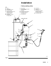
Fig. 2 is only a guide for selecting and installing sys-
tem components and accessories. Contact your Graco
distributor for assistance in designing a system to suit
your particular needs.
Air and Fluid Hoses
Be sure all air hoses (H) and fluid hoses (N and P) are
properly sized and pressure-rated for your system.
Use only electrically conductive hoses. Fluid hoses
must have spring guards on both ends. Use a whip
hose (P) and a swivel (R) between the main fluid
hose (N) and the gun (S) to allow freer gun movement.
Mounting Accessories
Mount the pump (A) to suit the type of installation
planned. Fig. 2 illustrates a wall mount system. Pump
dimensions and the mounting hole layout are shown
on page 27.
If you are using a floor stand, refer to its separate
manual for installation and operation instructions.