


7307906
Installation
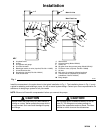
D Wall Bracket: Use the wall bracket (J) for wall
mounting the Universal pump. This wall bracket is
sized to fit any Graco pump designed to use a 2-in.
bung adapter. Order Part No. 203987.
D Runaway Valve: Install a pump runaway valve to
shut off the air to the pump when the pump acceler-
ates beyond the pre-adjusted setting. A pump that
is in a runaway condition can be seriously dam-
aged.
Never allow the pump to run dry of the fluid being
pumped. A dry pump quickly accelerates to a high
speed, possibly damaging itself, and it may get
very hot.
CAUTION
D Bleed-Type Master Air Valve: Install a bleed-type
master air valve (E) to relieve air trapped between it
and the motor when the valve is closed. To order a
300 psi (2.1 MPa, 21 bar), 1/4-in. npt(f) bleed-type
master air valve, order Part No. 110223.
D Suction Kit: The suction kit (L) is for use with the
wall-mounted Universal pump, and it includes a
drum tube and hose. To order a suction kit, order
Part No. 213099.
D Air Motor Lubricator: The air motor lubricator (D)
provides automatic air motor lubrication. To order a
250 psi (1.7 MPa, 17.4 bar) 1/4-in. npt(f) air motor
lubricator, order Part No. 110148.
D Air Regulator and Gauge: Use the air regulator and
gauge (C) to control air pressure and pump speed.
To order a 0 to 200 psi (0 to 1.4 MPa, 0 to 14 bar)
regulated pressure range (300 psi [2.1 MPa,
21 bar] maximum), 1/4-in npt(f) air regulator and
gauge, order Part No. 110147.
D Air Filter: The air filter (B) removes harmful dirt and
moisture from the compressed air supply. To order
a 300 psi (2.1 MPa, 21 bar), 1/4-in npt(f) air filter
(20-micron element), order Part No. 110146.
D Air and Fluid Shutoff Valves: Install air shutoff
valves (A) and fluid shutoff valves (H) as shown to
isolate the pump while you are servicing it.
D Quick-Disconnect Coupler and Nipple: The quick-
disconnect coupler and nipple (not shown) are used
to quickly disconnect the air supply. Attach the
coupler (Part No. 208536) to the pump air inlet
hose, and install the nipple (Part No. 169970) to the
pump air inlet (P).
D Thermal Relief Kit: Install the thermal relief kit on
the dispensing valve side of the pump to assist in
relieving pressure in the pump, hose, and dispens-
ing valve due to heat expansion. To order a 600 psi
(4.2 MPa, 41 bar) Thermal Relief Kit, order Part No.
237601.