


10 307906
Service
NOTE: Clean and inspect all parts for wear or damage
when disassembled. Replace parts as needed. Repair
Kit 247431 is available. For the best results, use all
the parts in the kit. Parts included in the kit are marked
with an asterisk in the text, figures, Parts Drawing,
and Parts List.
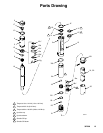
Intake Valve
See the Parts Drawing on page 13.
1. Relieve the pressure.
WARNING
To reduce the risk of serious injury whenever you
are instructed to relieve pressure, always follow the
Pressure Relief Procedure on page 8.
2. Unscrew the valve housing (21). Remove the
o-ring (22*), ball (23), and retainer (20).
3. Inspect the parts for wear or damage. If the ball is
nicked, replace it. Apply liquid sealant to the male
threads, and reassemble.
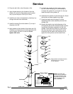
Air Motor
See Fig. 3.
1. Relieve the pressure.
WARNING
To reduce the risk of serious injury whenever you
are instructed to relieve pressure, always follow the
Pressure Relief Procedure on page 8.
2. Remove the air hose and fluid hoses.
3. Place the air motor base (5) in a vise.
WARNING
To reduce the risk of injury from trapped air pres-
sure when servicing the air motor, always remove
air cap (2) from air cylinder (4) before removing air
cylinder from base (5).
4. Remove the air cap (2). Gently pry the coils of the
spring (17) to remove the spring. Check the spring
for wear or damage, and replace as needed.
5. Use a strap wrench to unscrew the air cylinder (4)
from the base (5).
6. Unscrew the air piston assembly (15) from the
piston rod (10). Use pliers on the air exhaust plate
(15c*) and a wrench on the piston rod. See the
Piston Detail in Fig. 3.
NOTE: Old, cured thread sealant on the piston rod
threads makes it necessary that you use tools to
remove the air piston assembly from the piston
rod. Do not use these tools when you screw
the air piston assembly onto the piston rod.
7. Disassemble the air piston assembly (15). See the
Piston Detail in Fig. 3. Clean all parts, and inspect
them for wear or damage. If any valve plate
spacers are damaged, replace all three in order to
maintain the correct clearance between the valve
plates and seals.
8. Check the spring (8) for wear or damage, and
replace as needed.
9. Apply sealant, such as LoctiteR green, to the
threads of the screws. Assemble the parts as
shown in the Piston Detail in Fig. 3. Torque the
screws to 10 to 14 in-lb (1.3 to 1.6 N-m).
Displacement Pump
See Fig. 3, and see the Parts Drawing on page 13.
WARNING
Do not cycle the pump with any parts disassemb-
led. See the Moving Parts Hazard on page 4.
1. Use a strap wrench on the fluid cylinder (24) to
unscrew it from the motor base (5). Pull down on
the piston rod (10) until you have access to the
fluid piston assembly (19).
2. Stand the fluid piston assembly (19) in a vise, and
remove the piston rod (10).
3. Unscrew the fluid piston (19) from the piston
rod (10), and be careful not to drop the ball (18).
Remove the piston rod the rest of the way from the
base.
4. Remove the shaft seal (16*), wiper ring (11*), and
the gasket (9*) from the top of the motor base (5).
5. Reach inside the opening of the air motor base (5)
to remove the o-ring (26*). Carefully remove the
wiper ring (11*) and the seal (12*) from the motor
base.
6. Carefully inspect the smooth inner surface of the
fluid cylinder (24) for scoring or irregular surfaces.
Such damage causes premature packing wear and
leaking, so replace the part if needed.
7. Lubricate and install the new shaft seal (16*),
wiper ring (11*), and gasket (9*), seal (12*), wiper
ring (11*), and o-ring (26*) into the base.
8. Lubricate the new seal (19b*), and install it on the
fluid piston (19c).
9. Install washer (19a) onto fluid piston (19c).