


6 307906
Installation
Grounding
Proper grounding is an essential part of maintaining a
safe system.
To reduce the risk of static sparking, ground the pump.
Check your local electrical code for detailed grounding
instructions for your area and type of equipment. Be
sure to ground all of this equipment:
D Pump: Use a ground wire and clamp as shown in
Fig. 2.
D Air compressor: Follow the manufacturer’s recom-
mendations.
D Object being dispensed to: Follow the local code.
D Fluid supply container: Follow the local code.
D To maintain grounding continuity when flushing or
relieving pressure, always hold a metal part of the
dispensing valve firmly to the side of a grounded
metal container, then trigger the valve.
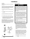
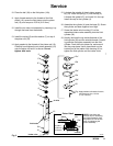
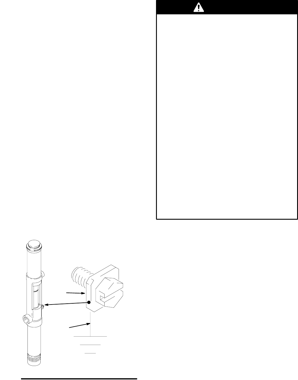
To ground the pump, remove the ground screw (Z)
and insert through the eye of the ring terminal at end of
ground wire (Y). Fasten the ground screw back onto
the pump and tighten securely. Connect the other end
of the wire to a true earth ground. To order a ground
wire and clamp, order Part No. 222011.
Y
Z
05941B
Fig. 2
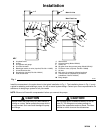
System Accessories
Three accessories are required in your system:
bleed-type master air valve, fluid drain valve, and
grounding wire. Additionally, for permanent installa-
tions, a thermal relief kit is required. These acces-
sories help reduce the risk of serious bodily injury,
including fluid injection, splashing in the eyes or on
the skin, injury from moving parts if you are adjust-
ing or repairing the pump, and explosion from
static sparking.
D The bleed-type master air valve (E) relieves air
trapped between it and the air motor after the
air supply is shut off. Trapped air can cause the
air motor to cycle unexpectedly, causing serious
injury if you are adjusting or repairing the pump.
As an alternative, use a quick-disconnect
coupler and fitting. Install them near the pump
air inlet within easy reach from the pump.
D The fluid drain valve (N) assists in relieving fluid
pressure in the displacement pump, hoses, and
dispensing valve. Triggering the valve to relieve
pressure may not be sufficient.
D The ground wire (G) reduces the risk of static
sparking.
D The thermal relief kit (R) assists in relieving
pressure in the pump, hose, and dispensing
valve due to heat expansion.
WARNING
D Extension Tubes: Pump models 222103 and
222104 have extensions tubes. An extension tube
may be added to the Universal pump for use in
submerged applications. To install, apply PTFE
tape to the female threads at the top of the tube.
Thread the tube tightly into the intake housing of
the Universal pump. Also, install a bung adapter. To
order a standard 2-in. bung adapter, order Part No.
222308.
D Air and Fluid Hose Kits (F): An 18-in. kit for wall-
mounted pumps and a 6-ft. kit for drum-mounted
pumps are available. Use a minimum 1/4-in. ID air
supply hose between the pump air inlet and the air
accessories. To order a kit with 1/4-in. air hose,
1/4-in. swivel elbow, 3/4-in. fluid hose, and 3/4-in.
swivel elbow, order one of the kits below:
222118 18-in. (0.4 m) hose kit for wall-mounted
pumps
222119 6-ft (1.8 m) hose kit for drum-mounted
pumps