


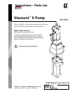
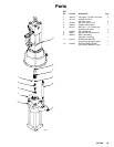

6 307160
Installation
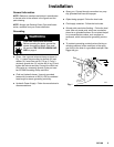
Mount the pump to suit the type of installation planned.
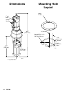
Pump dimensions and mounting hole layout are shown
on page 14.
CAUTION
The hydraulic supply system must be kept clean at
all times to avoid damage to the motor and hydraulic
power supply. Blow out all hydraulic lines with air and
flush thoroughly with compatible solvent before
connecting the lines to the motor.
Always plug the hydraulic inlets, outlets, and lines
when disconnecting them for any reason, to avoid
introducing dirt and other contaminants into the sys-
tem.
Filters
Be sure that your hydraulic power supply is equipped
with a suction filter to the hydraulic pump and a system
return line filter of 10 micron size.
Carefully follow the manufacturer’s recommendations
on reservoir and filter cleaning, and periodic changes
of hydraulic fluid. Use only Graco-approved hydraulic
oil.
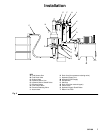
Hydraulic Lines
Connect a 3/4 in. minimum ID hydraulic supply line (L)
to the 3.4 npt inlet of the hydraulic motor. See the
Typical Installation on page 7. Connect a 1 in. mini-
mum ID return line (D) to the 1” npt return port on the
hydraulic motor.
On the hydraulic supply side (C), install the following
accessories shown in Fig. 2, using adapters as neces-
sary.
D A shutoff valve (E) isolates the pump for service.
D A fluid pressure gauge (F) to monitor hydraulic oil
pressure to the motor and to avoid overpressurizing
the motor or displacement pump, and a pressure-
and temperature-compensated flow control
valve (G) to prevent the motor from running too
fast and possibly damaging itself.
D A pressure reducing valve (H), with a drain
line (K) running directly to the hydraulic return
line (D).
D An accumulator (J) to reduce the hammering
effect caused by the motor reversing direction.
D A shutoff valve (E) isolates the pump for service.
CAUTION
Do not exceed 10 gpm (37.8 liter/minute) volume to
avoid pump stalling.
Drip Pan
The hydraulic motor is equipped with a drip pan to
collect any leakage that might occur. connect a 1/4 in.
ID drain hose (Q) to the barbed hose fitting on the drip
pan.
Drain Valve
Install a high pressure fluid drain valve (B) near the
pump fluid outlet to relieve fluid pressure in the dis-
placement pump and hose during shutdown.
WARNING
The fluid drain valve (B) is required in your system
to help reduce the risk of serious bodily injury,
including fluid injection and splashing in the eyes or
on the skin if you are adjusting or repairing any part
of the system. Triggering the gun to relieve pres-
sure may not be sufficient.
Fluid Supply Lines
Connect a grounded fluid supply line to the 1–1/2” npt
fluid outlet on the displacement pump. Attach a fluid
supply line to the 2” npt pump fluid intake.
If you are pumping through a long hose, or if the fluid
being pumped is compressible, giving an accumulator
effect, install a check valve at the pump outlet. Be sure
that the check valve selected is capable of handling
the flow and pressure developed in your system.