


12 307160
Service
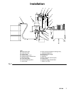
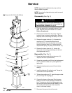
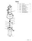
Fig. 3
06640
1
11
8
7
1
1
12
3
6
5
T
4
9
1
Torque to 40–50 ft-lb (54–68 NSm)
NOTE: To service the displacement pump, refer to
manual 308043, supplied.
NOTE: To service the hydraulic motor, refer to manual
308158, supplied.
Disassembly (See Fig. 3)
WARNING
To reduce the risk of serious injury whenever you
are instructed to relieve pressure, always follow the
Pressure Relief Procedure on page 8.
1. Flush the pump with a compatible solvent, if pos-
sible. Stop the pump at the bottom of its stroke.
Relieve the pressure.
2. Disconnect the hoses from the pump. Plug the
hydraulic lines to prevent contamination. Remove
the pump from its mounting and clamp it in a vise.
3. Remove the upper cotter pin (1). Unscrew the
coupling nut (7). Unscrew the three tie rod
locknuts (3), then unscrew the three tie rods (6)
from the hydraulic motor (11). Carefully pull the
displacement pump (12) away from the motor (11).
4. Remove the lower cotter pin (1). Loosen the
locknut (4). Unscrew the connecting rod (9) from
the displacement rod (T).
Reassembly (See Fig. 3)
1. Screw the three tie rods (6) into the motor (11).
Torque to 40–50 ft-lb (54–68 NSm).
2. Screw the connecting rod (9) into the displacement
rod (T). Install the cotter pin (1) and tighten the
locknut (4).
3. Guide the displacement pump (12) onto the tie
rods (6).
4. Install the locknuts (3) on the tie rods. Torque the
nuts to 40–50 ft–lb (54-68 NSm).
5. Tighten the coupling nut (7). Insert the upper cotter
pin (1) through the coupling (8)
6. Connect the hoses to the pump. Run the pump
slowly to be sure it runs smoothly and does not
bind. If necessary, adjust the displacement pump
tie rods and locknuts (see manual 308043), or the
tie rods (6) and locknuts (3) which attach the
motor, to eliminate binding.
7. Reconnect the ground wire to the motor.