Schematic Diagram
oo
1. The air conditioner is operable within the temperature ranges from-7 c~43 c.
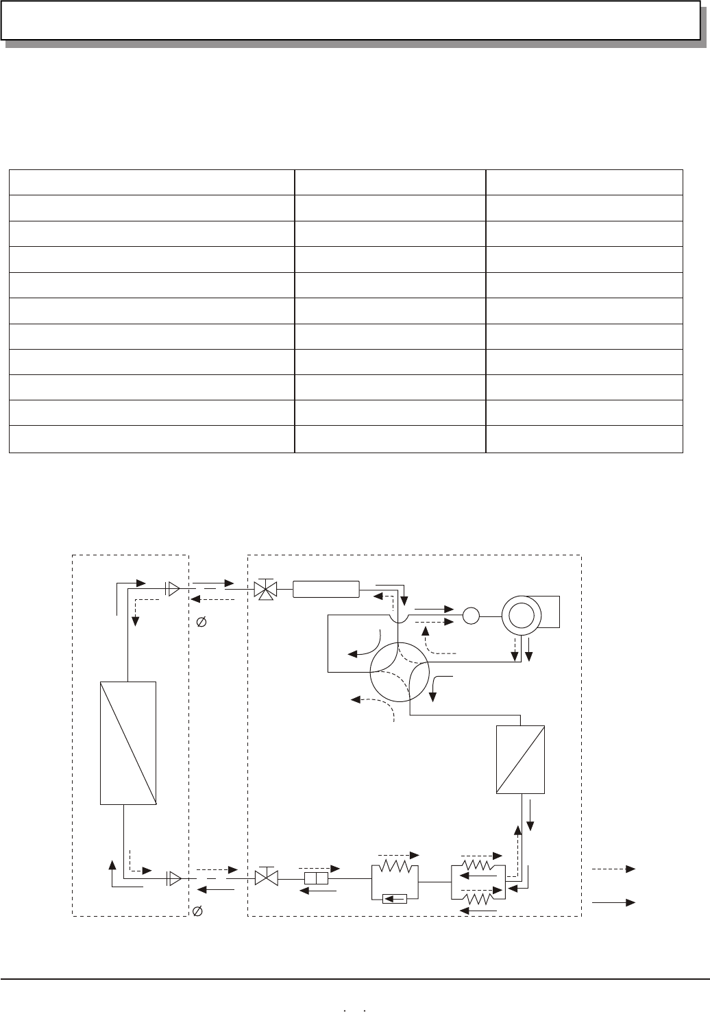
3. REFRIGERANT FLOW DIAGRAM
KFR-2601GW/BPE
AC 230V
¡£
8m/80
15m
50Hz
AC 160-253V
0.96kW/1.40kW
2.6kW/3.6kW
3
420m /h
R22/0.72kg
7.5kg/35.0kg
2. Main specifications of the product
type
Rated voltage
Frequency
voltage range
power consumptionof input(cooling/heating)
power (cooling/heating)
Air flow (high)
Refrigeration dose/consumption
Weight (indoor unit/outdoor unit)
Maximum remote control range/angle range
Maximum length of the connect tube
KFR-2801GW/BPE
AC 230V
¡£
8m/80
15m
50Hz
AC 160-253V
1.08kW/1.45kW
2.8kW/3.8kW
3
450m /h
R22/0.73kg
7.5kg/35.0kg
Q.D
6.35mm
(1/4")
Indoor unit
Heat exchanger
Narrow tube
Wide tube
Outdoor unit
4-way valve
Accumulator
Compressor
Heat exchanger
Capillary tube
Narrow
service
valve
tube
Cooling cycle
Heating cycle
Check valve
Capillary tube
Strainer
Narrow
service
valve
tube
Q.D
9.52mm
(1/2")
Muffler
19


