MHP-TN USER INSTRUCTIONS ENGLISH 71576313 - 02/07
Page 23 of 28 flowserve.com
If a check shows a bad running of the
motor pump unit, the user must:
a) Refer to the "fault finding chart" chapter
7 of this leaflet to apply the recommended
solutions.
b) Ensure that your equipment corresponds to
the arrangements of this leaflet.
c) ContactFlowserve after-sales Department if
the problem persists.
6.2.4 Gland packing
6.2.4.1 Pump fitted with a packed gland
A well run in and correctly adjusted packing gland
requires little maintenance. If, after some time, the
leakage becomes too great, the gland should be
tightened again in order to return these to a normal
level.
If re-tightening is not possible, new packing must
be installed.
6.2.4.2 Gland packing inspection and removal
a) Remove the shield guards.
b) Slide back the gland.
c) Remove the packing rings with an extractor
designed for this purpose (including the
lantern ring if it exists; note its position and its
direction of rotation).
d) Inspect the state of the sleeve surface; the
presence of many marked grooves will
indicate that it must be replaced.
e) Carefully clean the different pieces of the
packing gland.
6.2.4.3 Gland packing fitting
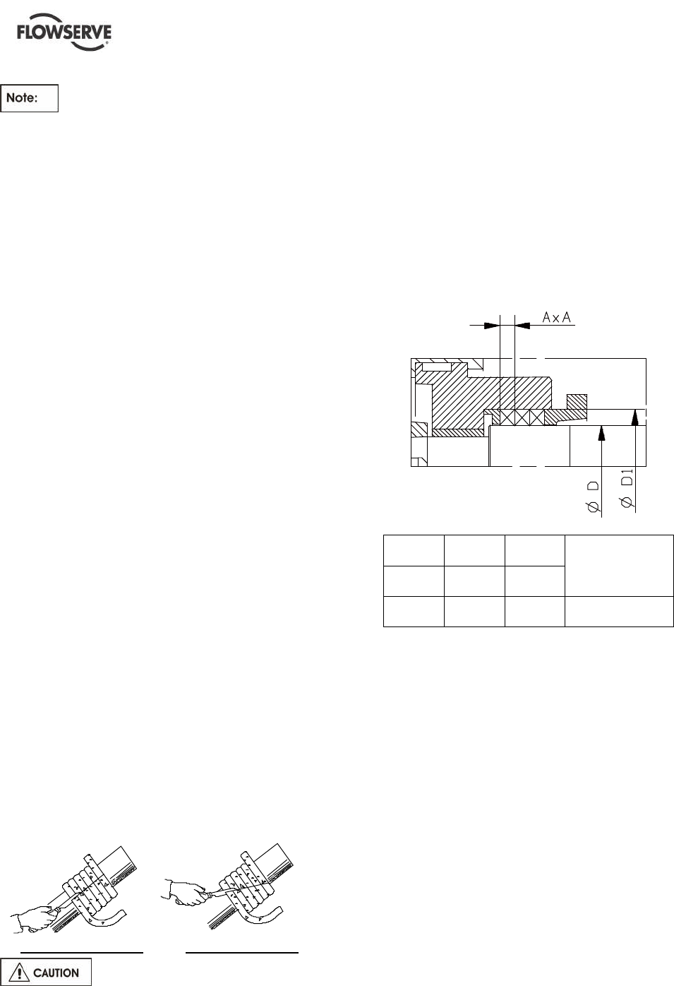
If the packing is supplied as cord the packing must
be cut so that the external diameter is lightly
tightened and there is an initial gap between the
sleeve and the packing ring.
For that purpose, wind the packing helically around
the shaft sleeve or a chuck of the same diameter.
(Take precautions to avoid damaging sleeve).
Example of straight cut Example ofbevel cut
Ensure a tightening on the stuffing
box housing and not on the sleeve.
SETTING OF PACKING
Follow the instructions:
a) Assemble of the packing in S.
b) Stagger by about 90° between two rings.
c) Assemble packing after packing.
After setting the last packing ring, secure the
packing with the gland and tighten the nut by
hand.
After tightening, the shaft should turn by hand as
easily as before the setting of the packing.
D D1 A x A
mm
(in.)
mm
(in.)
mm
(in.)
Nb x length
in mm
(in.)
55
(2.17)
76
(2.99)
10
(0.39)
4 x207
(4 x 8.15)
6.2.5 Internal coating
If the pump has an internal coating, this coating
must be inspected periodically. Any wear or cracks
of the coating found must be immediately repaired.
Failure to do this may lead to accelerated wear of
the coating during operation and corrosion of the
exposed base metal, depending on the material
and pumped liquid.
Special attention must be paid to the coating
edges. Any loss of coating material is considered
to be normal wear and tear on the pump and is not
considered as warranty.
Flowserve has applied the coatings according to
the supplier's instructions but will not be held
responsible for coating wear or cracks that may
develop over time.


