


S
hertech Operating Instructions, Performance,
S
pecifications and Parts Manual
9
Form L-4083 (1/06)
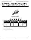
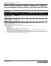
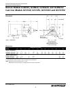
Bronze Models GCBN2V, GCBN3V, GCBN22V and GCBN33V
Cast Iron Models GCCV2V, GCCV3V, GCCV22V and GCCV33V
NOTE: If seal rubber has become bond-
ed to the shaft, use a pliers to remove
the seal (Ref. No 10) and replace with a
new seal assembly. Refer to INSPECTION
procedures below.
5. Remove the seal assembly spring
and metal seat.
6. Remove external retaining ring (Ref.
No. 9) from the shaft (Ref. No. 5)
using external snap-ring pliers
(2
1
⁄2” legs).
7. Remove the gear assembly and drive
shaft (Ref. No. 4 & 5).
Pump Inspection
Inspect components for signs of
excessive wear.
Excessive wear of the pump will usually
show up as degradation of performance.
This can be seen by the flow dropping
off under pressure, excessive noise
and/or excessive wear inside the pump.
Gear pump components are precision
fit. When the gears are worn, so is the
body, shafts, bushings or shaft pockets
and housing. At that point, the pump
head should be replaced.
8. Assemble the pump in reverse order
of disassembly. Tighten cover screws
(Ref. No. 3) in opposing sequence.
As the cover (Ref. No. 2) is incr
e-
mentally tightened, the shaft
(Ref. No. 5) should be periodically
tur
ned. This ensures cover-to-body
alignment and pr
events binding
of shaft.
9. Assemble pump to motor. (See
Assembly 3 through 5.)
10. All pumps must be primed before
start-up and the seal chamber needs
to be filled.
Do not run pump
dry, as permanent
damage to the pump gears, seal, and
bearings will result. Suction pressure should
never be greater than the discharge pressure.
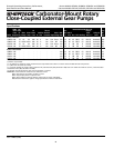
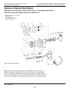
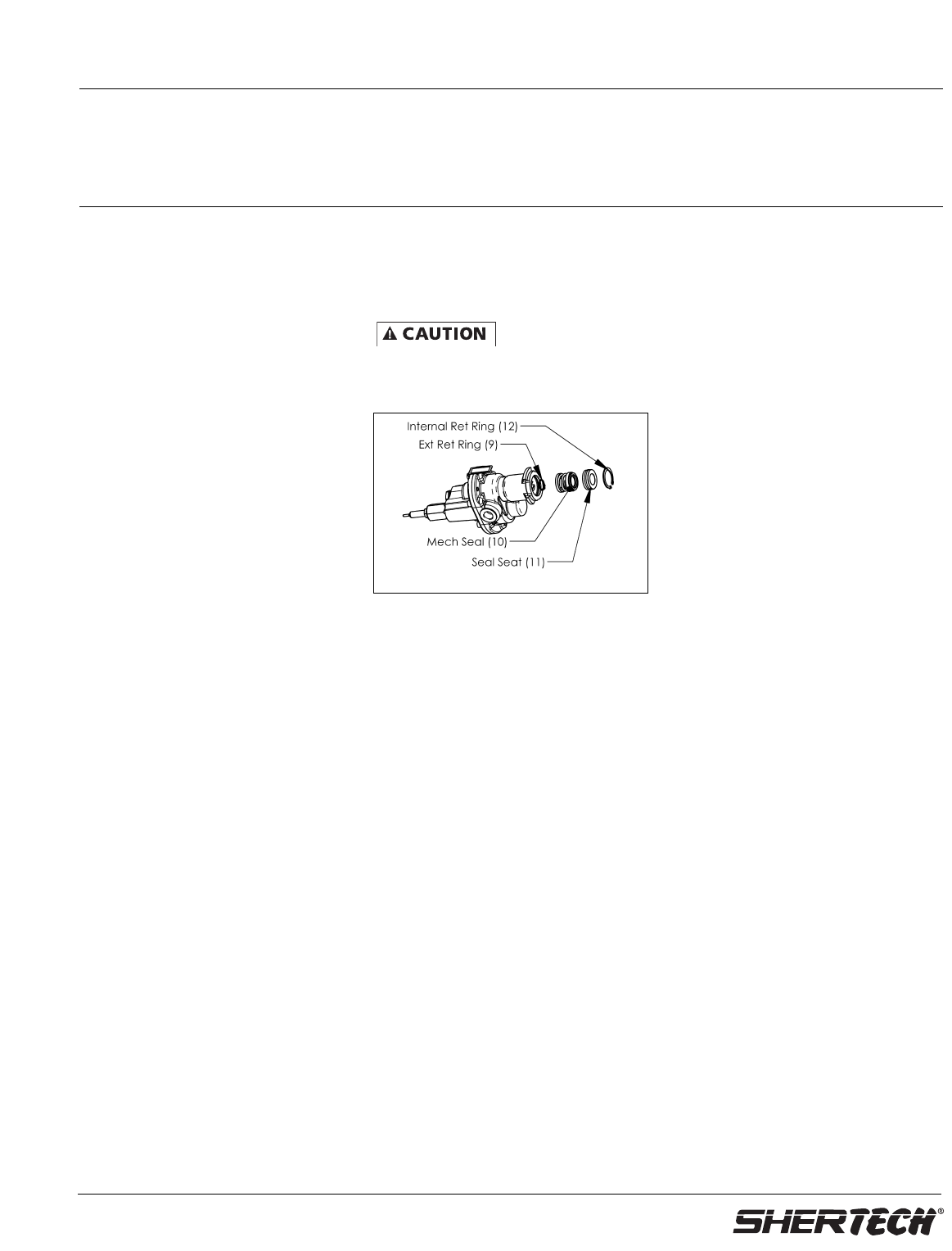
Mechanical Seal Replacement (Refer to
Figures 6 & 7 for parts identification.)
1. Remove pump from motor, if not
already done.
2. Remove snap ring (
Ref. No. 12
). Pry
out seal seat (
Ref. No. 11
). Pull
mechanical seal (
Ref. No. 10
) off shaft.
(See Assembly 3 through 5.)
3. Reinstall new mechanical seal (
Ref.
No. 10
) on drive shaft using water as
a lubricant. Do not push on carbon
face of new mechanical seal. Push
with a hallowed out wood dowel or
piece of cardboard.
4. Install seal seat (
Ref. No. 11), with
water as a lubricant, on the O-ring
with shiny white ceramic face facing
the carbon seal
(
Ref. No. 10
) without
touching either of the seal faces.
Scratching the seal faces will cause
the seal to leak. Using anything
other than water as a lubricant,
when installing seal and seat, may
cause seal to leak.
NOTE: The carbon and ceramic seal
faces spin against each other providing
for the functional seal. The seal ceramic
seat o-ring is not the functional seal,
but its purpose is to hold the seal
ceramic seat in place.
5. Reinstall the snap ring (
Ref. No. 12
).
Relief Valve Disassembly and Assembly
(Refer to Figure 7 for parts
identification.)
1. Standard models are equipped with
a pressure relief valve. Remove the
relief valve cap (
Ref. No. 15
)
and
O-ring
(
Ref. No. 19)
.
2. Remove the spring (Ref. No. 22)
and piston (Ref. No. 23). A worn
or broken relief valve is a sign of
excessive pump wear. The pump
head should be replaced.
3. Assemble the relief valve in reverse
or
der.
Figure 6 - Mechanical Seal Replacement