


7
S
hertech Operating Instructions, Performance,
S
pecifications and Parts Manual
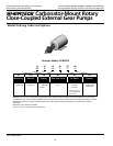
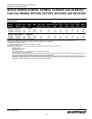
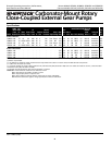
Bronze Models GCBN2V, GCBN3V, GCBN22V and GCBN33V
Cast Iron Models GCCV2V, GCCV3V, GCCV22V and GCCV33V
Form L-4083 (1/06)
6. Be certain all suction piping connec-
t
ions are airtight.
N
OTE:
A
ssure airtight pipe connections
with the use of a pipe joint sealant.
DISCHARGE
1. Attach discharge piping to the
discharge outlet.
Support pump and
piping during assem-
bly and after installation. Failure to do so may
cause piping to break, pump to fail, motor
bearing failures, etc. All of which can result
in property damage and/or personal injury.
NOTE: Should the pump need to be
self-draining, the pump head should be
mounted in the vertical position with
the suction port facing down. When
pumping high viscosity fluids, the
vertical position can be used with the
suction port facing up and the pump
mounted under the source. Increasing
the suction pipe size and eliminating
bends and elbows also assists in pump-
ing high viscosity fluids. Max. viscosity is
500 SSU at 1725 RPM.
2. If a shut-off valve or handgun is
required in discharge line, provide
a pressure relief valve for pump
pr
otection.
Shutting off
discharge without
providing pressure relief can cause extreme
over-pressure which can result in pump
and/or motor failur
e. Do not exceed 100 PSI
pump or system pressure.
3. Operation under shut-off discharge
conditions will overheat and
damage pump.
NOTE: Globe valve or other restrictive
valves should not be used as shut-off
mechanism as they are restrictive in
nature and will seriously affect pump
performance.
4. After all piping and controls (not
supplied with unit) have been
installed, unit is ready for operation.
Operation
Do not run pump dry,
as permanent damage
to the pump gears, seal, and bearings will
result. Suction pressure should never be
greater than the discharge pressure.
1. All pumps must be primed before
start-up. Never operate a pump
unless it is secured to a solid
foundation.
2. Gear pumps are built to very close
tolerances and this tolerance must
not be altered. The liquids must,
therefore, be free of all abrasives.
Sand, silt, wettable powders, etc.
must be avoided.
NOTE: Cast iron pumps are for oil-based
fluids only.
3. When pumping a more viscous
(beyond 500 SSU) liquid, a slower
speed, a larger pipe size pump,
and possibly a larger motor should
be selected.
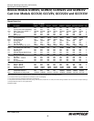
NOTE: See performance chart for Max.
Torque.
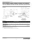
4. Recheck motor rotation. Proper
motor/pump rotation is clockwise
(CW) looking at the motor shaft
(See Figure 3).
5.
On all models, the pressure relief
valve is always on discharge side
(See Figure 3).
PRESSURE RELIEF VALVE
6. Standard model rotary gear pumps
are supplied with a built-in pressure
relief valve. The valve may be adjust-
ed and used to set system operating
pr
essur
e, or used as a system relief
valve to prevent pump and motor
damage that can occur when dis-
charge line is closed off. This relief
valve is not factor
y set. Extended
operation (over one minute) under
shut-off conditions could cause pump
to overheat, leak, and damage itself.
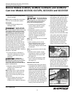
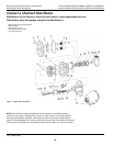
7. To increase the relief valve pressure
setting, remove protective cap,
loosen lock nut, then turn the set
screw (Figure 4 & 7, Ref. No. 18) in
(
clockwise). Turning the set screw
out (counterclockwise) will reduce
the pressure setting. When desired
pressure is achieved, tighten lock
nut and reinstall protective cap.
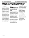
8. The pressure relief valve can be
converted to an external relief. This
will allow the relief to dump back
to tank and allow longer periods of
relief without pump damage.
However, this is not a full-line relief
valve, and in cases where frequent
extended relief valve operation is
anticipated, a full-line size relief
valve should be piped in the dis-
charge line and connected either
back to the tank or well down-
stream of the pump suction inlet.
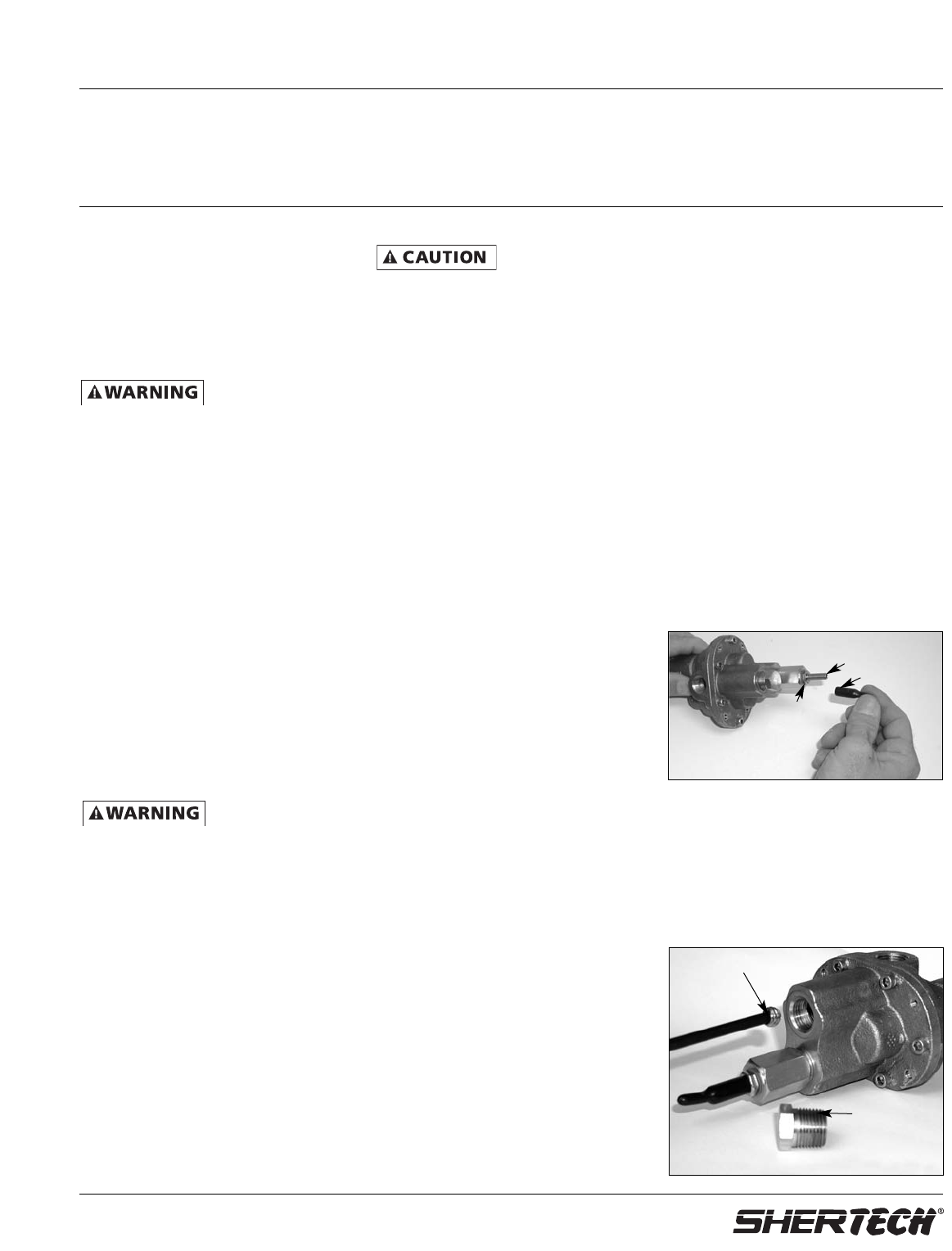
9. To convert the relief valve to exter-
nal relief, remove the 1/4 NPT pipe
plug from the pump cover (Figure 5
&
7, Ref. No. 13) and discard. This
plug is next to the relief valve. In
the bottom of the 1/4 NPT hole,
ther
e is a second drilled and tapped
Figure 4 - Pressure
Relief Valve Adjustment
Protective
cap
Adjust pressure
relief valve screw
Loosen
lock nut
Figure 5 - External Bypass Installation
Optional
external
bypass plug
Remove and
discard plug