


8
Operation (Continued)
h
ole of 1/4 size. An optional exter-
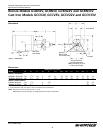
nal bypass plug (Figure 5 & 7, Ref.
No. 14 included) should be inserted
i
n this hole and bottomed out. The
open 1/4 NPT port must now be
piped back to the tank or well
downstream of the pump suction.
10. For operation of the pump with
pressure relief valve in reverse rota-
tion, the motor may be reversed,
allowing for reverse rotation.
Standard models are equipped with
pressure relief valves and the pump
can be run in reverse, however, the
pressure relief valve will not func-
tion. For continuous reverse rota-
tion, the cover plate must be r
otat-
ed 180˚. This is accomplished by
removing the six cover plate screws,
rotating the cover plate, and reat-
taching the screws. The relief valve
should now be on the opposite side.
This will allow operation of the
pump with a functioning pressure
relief valve in reverse rotation.
Maintenance
Make certain that the
power source is discon-
nected before attempting to service or disas-
semble any components! If the power discon-
nect is out of sight, lock it in the open position
and tag to prevent application of power.
GENERAL
Check the pump for pr
oper operation
daily, weekly, monthly, etc. If anything
has changed (pump noise, motor noise,
leaks, etc.) since the pump was new, the
pump should be removed, examined and
repaired if necessary. This is a difficult
motor/pump to repair, therefore, only
qualified electricians or service techni-
cians should attempt to repair this unit.
Improper repair and/or assembly can
cause problems with the electric motor
used with this unit. See General Safety
Information.
Retighten the ”V“ band clamp screw as
necessary. Use Loctite or similar thread
sealant if screw keeps coming loose.
Rotary gear pumps must be drained
completely if subject to freezing
temperature and should not be
operated until temperature permits.
To store the pump, place a small quantity
o
f light oil or some other storage preser-
vative compatible with your application
in the pump and rotate the shaft very
s
lowly to work the oil throughout the
gears and the body.
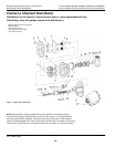
DISASSEMBLY AND ASSEMBLY
Refer to Figure 7 for parts identification
during disassembly and assembly.
[Assumes pump is separated fr
om
motor and that Oldham coupling
(Ref. No. 24) is removed.]
1. Remove screws (Ref. No. 3) and
cover (Ref. No. 2). Refer to
INSPECTION procedures below.
2. Lift out idler shaft (Ref. No. 8).
3. Remove internal retaining ring (Ref.
No. 12) from drive end of the pump
body (Ref. No. 1) using TruArc-type
internal snap-ring pliers.
4. Carefully pry out ceramic seat (Ref.
No. 11) and then seal (parts of
seal seat assembly using a suitable
hooked tool).
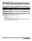
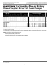
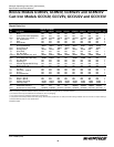
Bronze Models GCBN2V, GCBN3V, GCBN22V and GCBN33V
C
ast Iron Models GCCV2V, GCCV3V, GCCV22V and GCCV33V
S
hertech Operating Instructions, Performance,
S
pecifications and Parts Manual
Form L-4083 (1/06)
Carbonator-Mount Rotary
Close-Coupled External Gear Pumps