


HOW TO INSTALL YOUR GAS LOG SET
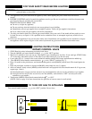
This log set must be installed by a qualified person and instructions must be followed exactly to ensure safe operation.
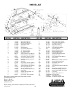
Your log set is packaged in three (3) boxes. The complete burner assembly is packaged in one box and the logs are packaged
in separate boxes.
GENERAL INSTALLATION
These logs require a minimum permanent free opening as stated in the chart on page 3 of these instructions, that must be
provided by either the fireplace chimney or the fireplace damper to vent the gases. The chimney damper must be fixed in a
manner which will maintain the minimum permanent vent opening at all times. This may be accomplished by installing a
screw bolt in the edge of the damper to prevent its closing or by a hole(s) in the damper. These logs must be installed only in
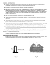
a vented fireplace with a working flue and constructed of noncombustible material. The minimum size fireplace in which
these logs are to be installed is:
BURNER ASSEMBLY AND INSTALLATION
1. Turn off gas supply to fireplace.
2. Ensure that fireplace is clean.
3. Remove complete burner assembly from box and place complete burner assembly on floor of fireplace with the
open side of the bottom pan facing the front of the fireplace.
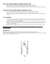
4. Position the burner assembly centered from side to side and as far toward the back of the fireplace as possible.
The fireplace will draft better with the burner unit toward the back of the fireplace. (Never place the burner
assembly more toward the front in larger fireplaces.)
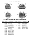
5. Remove logs from log box and place on burner assembly as described on page 5 under L
og Placement.
6. Visually inspect the position of gas log set in the fireplace as described above.
7. After you have visually inspected the position of the log set in the fireplace, remove logs from burner assembly
and proceed to connect gas supply.
CONNECTING GAS SUPPLY
There is a 3/8 flared fitting installed on your gas log set at the factory. Be sure fittings are the appropriate size on any
tubing that is to be connected to your gas log set. If using tubing that has to be cut and shaped, be sure to use the proper
tubing cutter and flaring tool. Also, be careful not to crimp the tubing when it is being bent to hook up the log set. A crimp in
this line could restrict the gas flow to the log set. If a crimp does occur, do not use the gas line. Gas resistant pipe compound
must be used on all threaded male connections, except brass to brass.
NOTE: During the first 2 to 3 hours of burning, the flame burning against the glowing log will
appear to be orange in color. After this burn in period this flame will turn completely blue and
almost invisible. You will then see mostly glow and no flame on the face of this glowing log,
which enhances the glow appearance.
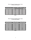
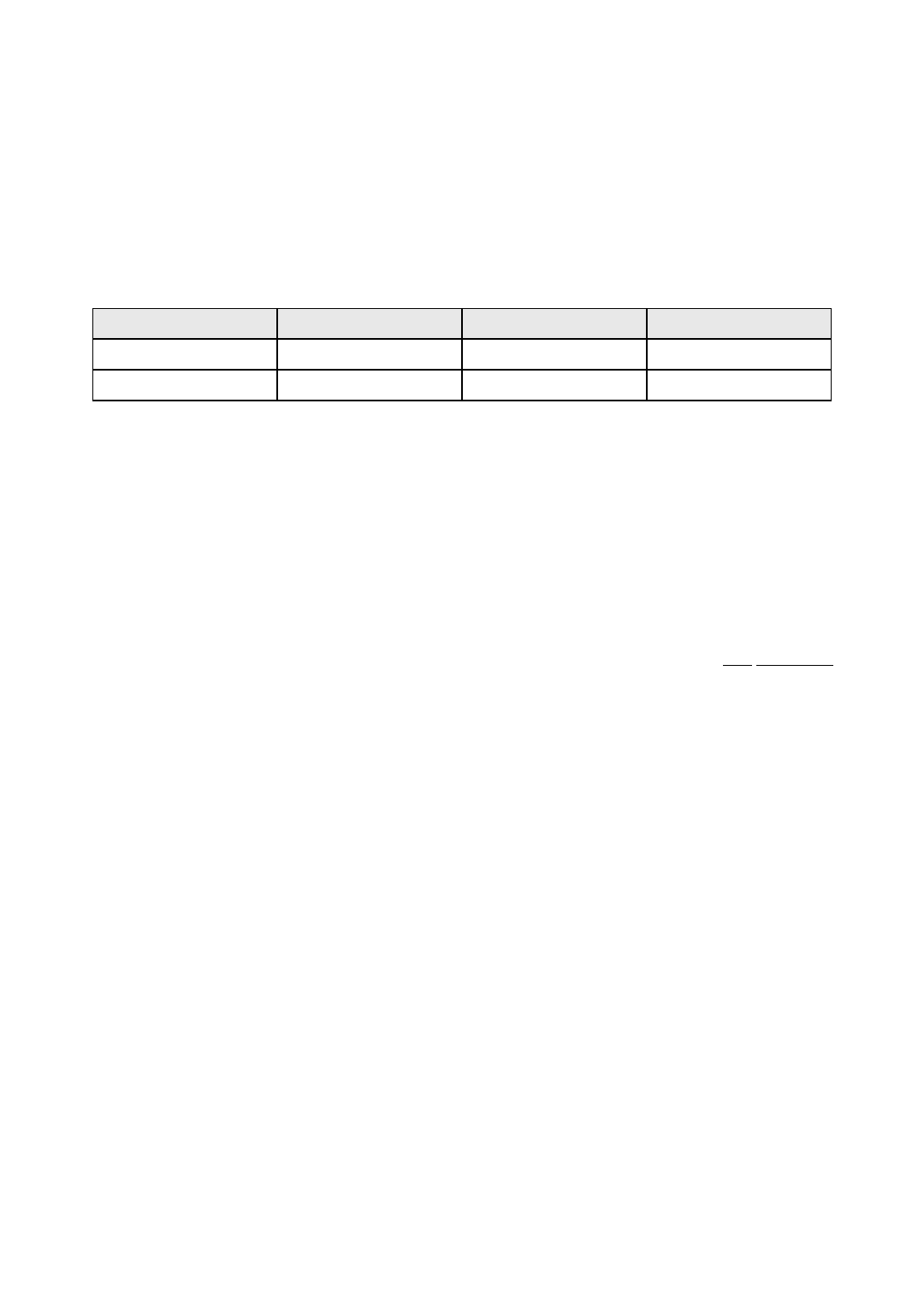
Log Set Size
18”
24”
Depth
14”
14”
Height
18”
18”
Front Opening Width
25”
36”
4