


35
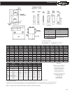
MODELS HD
Sizes 50 - 65 AF
T
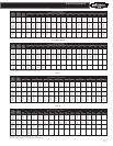
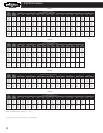
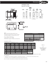
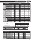
Dimensions
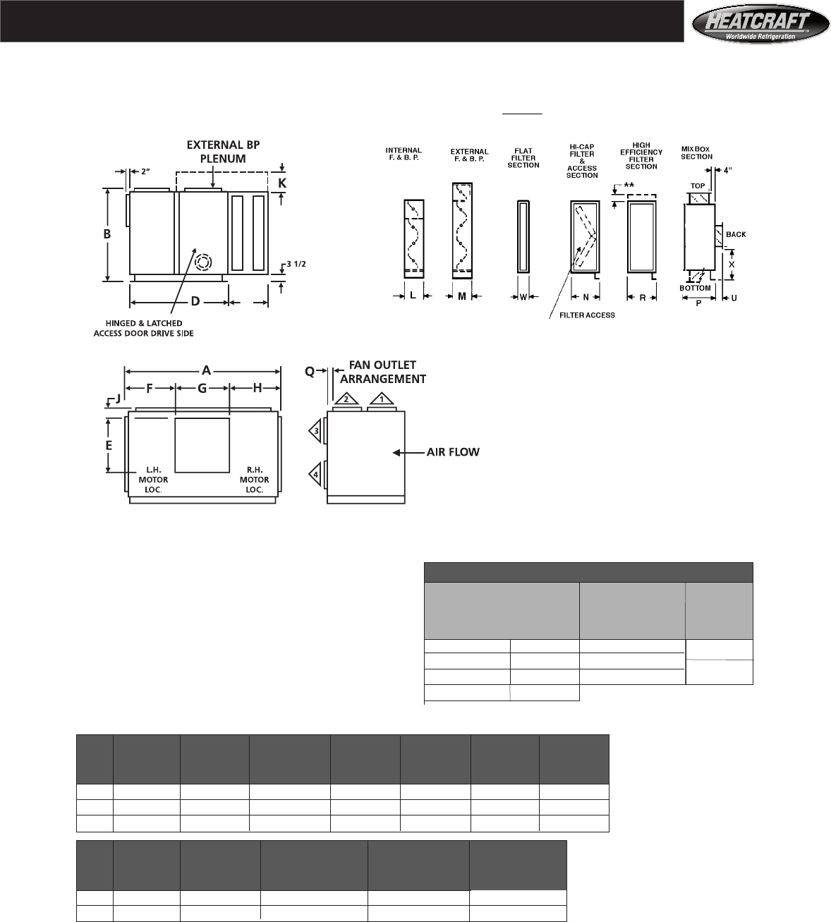
Notes:
Motor and connection locations (R.H. or L.H.) For All Units Sizes
determined when facing the front of the unit, with the T R** W
air blowing through the coil and into observer’s face.
Floor or platform mounting only.
Ceiling suspension is not available. 1 & 2 rows 6 3/8 22 6
Electric Heat: See page 6 for heater section dimensions. 3 & 4 rows 10 1/8 28
6 rows 12 5/8 44 8
8 Rows 15 5/8
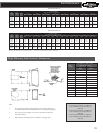
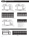
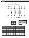
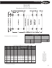
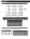
Arrangements Available:
Size 50 through 75 — Arrangements 1, 2, 3, 4^^
A B E F G J K
Unit air handler air handler fan discharge fan discharge fan discharge discharge external F&BP
Size width height length location width arrangement 3 added height HD Note
50 119 78 7/8 34 1/2 35 9/16 47 7/8 15 19 1/2
65 135 86 7/8 42 1/4 38 1/2 58 10 3/4 24 1/2 HD
75 135 98 7/8 42 1/4 38 1/2 58 22 3/4 24 1/2 HF(heating duty) unit
depth is dimension
L M^^ P Q+ X ‘D’ added to
Unit internal F&BP external F&BP Mixnoc discharge vertical locator, back dimension ‘T’.
Size section depth section depth arrangement 1 & 2 inlet, economizer
50 9 1/4 21 1/2 40 1/2 2 1/2 24 5/8
65 10 1/4 27 1/2 40 1/2 5 5/8 28 5/8
All dimensions are in inches.
AF = Airfoil Fan
+ Dimension “Q” is for Discharge Arrangement 2. For Discharge Arrangement 1, “Q” measures from corresponding side of unit.
^^ Arrangements 1 and 2 are not available with external face and bypass damper section.
Note: For double wall construction and internal isolation, please consult factory
** See page 29 for high efficiency filter section height and width.