


16
CAUTION: IF JOINTS BETWEEN THE FINISHED WALLS
AND THE FIREPLACE SURROUND (TOP AND SIDES)
ARE SEALED, A 300°
F. MINIMUM SEALANT MATE-
RIAL MUST BE USED. THESE JOINTS ARE NOT RE-
QUIRED TO BE SEALED. ONLY NON-COMBUSTIBLE
MATERIAL (USING 300° F. MINIMUM ADHESIVE, IF
NEEDED) CAN BE APPLIED AS FACING TO THE FIRE-
PLACE SURROUND. SEE THE DIAGRAM BELOW.
Hearth Extensions
A hearth extension may be desirable for aesthetic reasons.
However, ANSI or CAN/CGA testing standards do not require
hearth extensions for gas fireplace appliances.
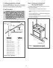
Installing the Trim
Combustible materials may be brought up to the specified
clearances on the side and top front edges of the fireplace,
but MUST NEVER overlap onto the front face. The joints
between the finished wall and the fireplace top and sides
can only be sealed with a 300° F. (149° C) minimum sealant.
Install optional marble and brass trim surround kits as
desired. Marble, brass, brick, tile, or other non-combustible
materials can be used to cover up the gap between the
sheetrock and the fireplace.
Do not obstruct or modify the air inlet/outlet grilles. When
overlapping on both sides, leave enough space so that the
controls can be accessed and the trim door and glass door
can be removed.
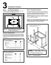
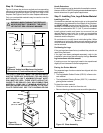
Step 11. Installing Trim, Logs & Ember Material
Figure 14.
Sealant Material
Placing the Ember Material
Two separate bags of ember material are shipped with this
gas fireplace:
The bag labeled Golden Ember (GE-93) is flame colo-
rant material.
The bag labeled Glowing Ember (050-721) is standard
glowing ember material.
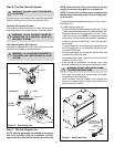
To place the ember material:
Lift the trim door up and out from the unit.
Remove the wing nuts and screws around the glass door.
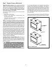
Figure 15. Glass Assembly
STUD
HEADER
FINISHED
WALL
SEAL JOINT
(300° F/149° C MIN.)
GLASS
ASSEMBLY
MOUNTING
STUD
GLASS CLIP
WING NUT
Positioning the Logs
If the gas logs have been factory installed they should not
need to be positioned.
If the logs have been packaged separately, refer to the
installation instructions that accompany the logs. Save the
log instructions with this manual.
If sooting occurs, the logs might need to be repositioned
slightly to avoid excessive flame impingement.
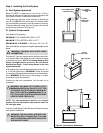
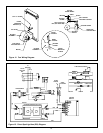
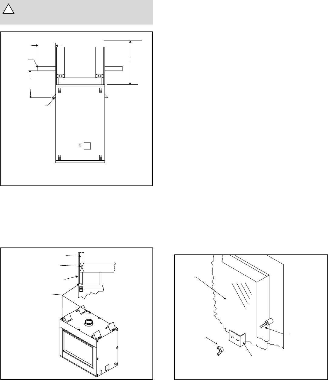
Step 10. Finishing
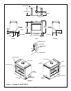
Figure 13 shows the minimum vertical and corresponding
maximum horizontal dimensions of fireplace mantels or other
combustible projections above the top front edge of the
fireplace. See Figures 2 and 3 for other fireplace clearances.
Only non-combustible materials may be used to cover the
black fireplace front.
WARNING: WHEN FINISHING THE FIREPLACE,
NEVER OBSTRUCT OR MODIFY THE AIR IN-
LET/OUTLET GRILLES IN ANY MANNER.
Figure 13.
Minimum Vertical and Maximum Horizontal
Dimensions of Combustibles above Fireplace
!
12"
MINIMUM
8" MAXIMUM
MANTLE
HOOD
31”
CEILING