


13
!
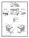
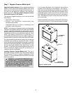
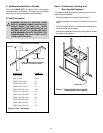
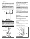
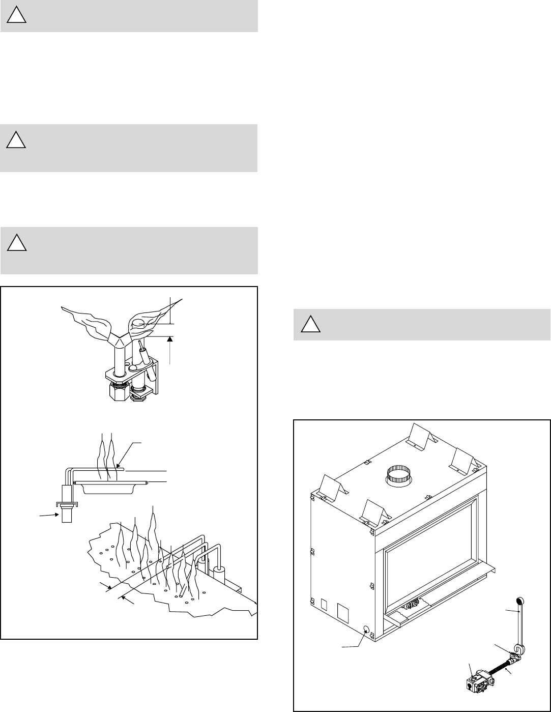
Figure 9. Gas Supply Line
At the gas line access hole, use insulation to re-pack
the space around the gas pipe.
Insert insulation from the outside of the fireplace and
pack the insulation tightly to totally seal between the
pipe and the outer casing.
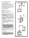
Step 7. The Gas Supply Line
NOTE: Have the gas supply line installed in accordance
with local building codes by a qualified installer
approved and/or licensed as required by the locality.
!
USE A WRENCH ON
SHUT-OFF VALVE WHEN
TIGHTENING GAS LINE
GAS VALVE
FLEX
CONNECTOR
MANUAL
SHUT-OFF VALVE
WARNING: THIS UNIT IS NOT FOR USE WITH
SOLID FUEL.
!
!
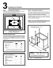
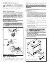
Step 6. The Gas Controls System
WARNING: DO NOT USE AN OPEN FLAME
TO CHECK FOR GAS LEAKS.
GAS
ACCESS
Two types of gas control systems are used with these models:
Standing Pilot Ignition and Direct Spark Ignition (DSI).
Standing Pilot Ignition System
This system includes millivolt control valve, standing pilot,
thermopile/thermocouple flame sensor, and piezo ignitor.
WARNING: 110-120 VAC MUST NEVER BE
CONNECTED TO A CONTROL VALVE IN A
MILLIVOLT SYSTEM.
Direct Spark Ignition (DSI) System
This system includes a 24V control valve, electronic module,
transformer, and spark ignitor/flame sensor.
WARNING: 110-120 VAC MUST BE WIRED TO
THE FIREPLACE JUNCTION BOX IN A DSI
SYSTEM.
NOTE: Before the first firing of the fireplace, the gas
supply line should be purged of any trapped air.
NOTE: Consult local building codes to properly size
the gas supply line leading to the 1/2 inch (13mm) hook-
up at the unit.
This gas fireplace is designed to accept a 1/2 inch (13mm)
gas supply line.
To install the gas supply line:
A listed (and State of Massachusetts approved) 1/2 inch
(13mm) tee-handle manual shut-off valve and a listed flex-
ible gas connector are connected to the 1/2 inch (13mm)
inlet of the control valve. NOTE: If substituting for these
components, please consult local codes for compliance.
Locate the gas line access hole in the outer casing of
the fireplace.
The gap between the supply piping and gas access hole
can be plugged with non-combustible insulation to pre-
vent cold air infiltration.
Insert the gas supply line through the gas line hole, and
connect it to the shut-off valve.
When attaching the pipe, support the control so that the
lines are not bent or torn.
After the gas line installation is complete, use a soap
solution to carefully check all gas connections for leaks.
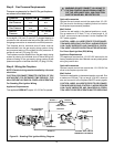
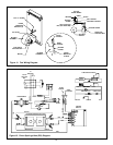
Figure 8. Gas Supply Line
3/8” (10mm)
STANDING PILOT
DSI IGNITION
3/16” (5mm)
CERAMIC
INSULATOR
IGNITOR
1/2” (13mm)