


14
!
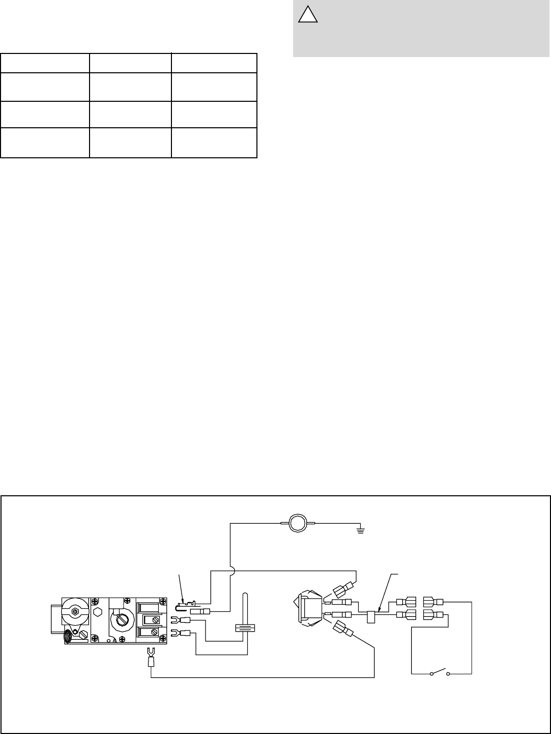
Step 9. Wiring the Fireplace
NOTE: Electrical wiring must be installed by a licensed
electrician.
CAUTION: DISCONNECT REMOTE CONTROLS IF YOU
ARE ABSENT FOR EXTENDED TIME PERIODS. THIS
WILL PREVENT ACCIDENTAL FIREPLACE OPERATION.
For Standing Pilot Ignition Wiring
Appliance Requirements
This appliance DOES NOT require 110-120 VAC to operate.
For Direct Spark Ignition (DSI) Wiring
Appliance Requirements
This appliance requires that 110-120 VAC be wired to the
factory installed junction box. Maintain correct polarity when
wiring the junction box.
Optional Accessories
Optional remote control kits require that 110-120 VAC be
wired to the fireplace junction box.
Wall Switch
Position the wall switch in the desired position on a wall. Run
a maximum of 25 feet (7.8m) or less of 16 A.W.G. minimum
wire and connect it to the fireplace ON/OFF switch pigtails.
CAUTION: LABEL ALL WIRES PRIOR TO DISCONNEC-
TION WHEN SERVICING CONTROLS. WIRING ERRORS
CAN CAUSE IMPROPER AND DANGEROUS OPERA-
TION. VERIFY PROPER OPERATION AFTER SERVICING.
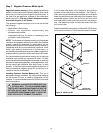
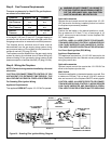
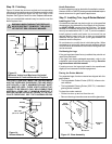
WHITE T2
BLACK S1
THERMOPILE
GAS VALVE
RED T1
3\16" PIGGYBACK
CONNECTOR
TH
TH
SWITCH
ON/OFF
THERMOSTAT OR REMOTE
OPTIONAL WALL SWITCH,
LIMIT SWITCH
OFF
ON
BLACK S2
HI-TEMP
GROUND
BLACK L1
BLACK L2
PIGTAIL
REMOTE SWITCH
TP
TP
Figure 10. Standing Pilot Ignition Wiring Diagram
Wall Switch
Position the wall switch in the desired position on a wall.
Run a maximum of 25 feet (7.8 m) or less length of 18
A.W.G. minimum wire and connect it to the fireplace ON/
OFF switch pigtails.
CAUTION: LABEL ALL WIRES PRIOR TO DISCONNEC-
TION WHEN SERVICING CONTROLS. WIRING ERRORS
CAN CAUSE IMPROPER AND DANGEROUS OPERA-
TION. VERIFY PROPER OPERATION AFTER SERVICING.
WARNING: DO NOT CONNECT 110-120 VAC TO
THE GAS CONTROL VALVE OR WALL SWITCH
OR THE APPLIANCE WILL MALFUNCTION
AND THE VALVE WILL BE DESTROYED.
Optional Accessories
Optional fan and remote control kits require that 110-120
VAC be wired to the factory installed junction box before
the fireplace is permanently installed.
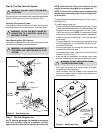
Step 8. Gas Pressure Requirements
Pressure requirements for Heat-N-Glo gas fireplaces
are shown in the table below.
Pressure Natural Gas Propane
Minimum 5.0 inches 11.0 inches
Inlet Pressure w.c. w.c.
Maximum Inlet 14.0 inches 14.0 inches
Gas Pressure w.c. w.c.
Manifold 3.5 inches 10.0 inches
Pressure w.c. w.c.
A one-eighth (1/8) inch (3 mm) N.P.T. plugged tapping is
provided on the inlet and outlet side of the gas control for a
test gauge connection to measure the manifold pressure.
The fireplace and its individual shut-off valve must be
disconnected from the gas supply piping system during
any pressure testing of the system at test pressures in
excess of one-half (1/2) psig (3.5 kPa).
The fireplace must be isolated from the gas supply piping
system by closing its individual shut-off valve during any
pressure testing of the gas supply piping system at test
pressures equal to or less than one-half (1/2) psig (3.5 kPa).