


37Heat & Glo • SL-550 / 750 / 950TV-D • 2053-985 Rev. J • 4/07
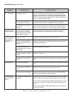
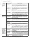
B. Intellifi re Ignition System
Symptom Possible Causes Corrective Actions
1. The ignitor/
module makes
noise, but no
spark.
a. Incorrect wir-
ing.
Verify “S” wire (white) for sensor and “I” wire (orange) for ignitor are con-
nected to correct terminals on module and pilot assembly. Reversed wires
at the module may cause system to make sparking noise, but spark may
not be present at pilot hood.
b. Loose connec-
tions or electri-
cal shorts in the
wiring.
Verify no loose connections or electrical shorts in wiring from module to pi-
lot assembly. Rod closest to pilot hood is ignitor. Verify connections under-
neath pilot assembly are tight; also verify connections are not grounding
out to metal chassis, pilot burner, pilot enclosure, mesh screen if present,
or any other metal object.
c. Ignitor gap is
too large.
Verify gap of igniter to pilot hood. The gap should be approximately .17
inch or 1/8 inch.
d. Faulty module. Turn ON/OFF rocker switch or wall switch to OFF position. Remove ignitor
wire “I” from module. Place ON/OFF Rocker switch or wall switch in ON
position. Hold ground wire about 3/16 inch away from “I” terminal on mod-
ule. If there is no spark at “I” terminal module must be replaced. If there is
a spark at “I” terminal, module is fi ne. Inspect pilot assembly for shorted
sparker wire or cracked insulator around electrode.
2. Pilot won’t
light, there is no
noise or spark.
a. Transformer
installed correctly.
Verify that transformer is installed and plugged into module. Check volt-
age of transformer under load at spade connection on module with ON/
OFF switch in ON position. Acceptable readings of a good transformer are
between 3.2 and 2.8 volts AC.
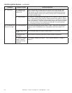
b. A shorted or
loose connection
in wiring confi gu-
ration or wiring
harness.
Remove and reinstall the wiring harness that plugs into module. Verify
there is a tight fi t. Verify pilot assembly wiring to module. Remove and
verify continuity of each wire in wiring harness.
c. Improper wall
switch wiring.
Verify that 110 VAC power is “ON” to junction box.
d. Module not
grounded.
Verify black ground wire from module wire harness is grounded fi rmly to
metal chassis of appliance.
e. Faulty mod-
ule.
Turn ON/OFF rocker switch or wall switch to OFF position. Remove ignitor
wire “I” from module. Place ON/OFF Rocker switch or wall switch in ON
position. Hold ground wire about 3/16 inch away from “I” terminal on mod-
ule. If there is no spark at “I” terminal module must be replaced. If there is
a spark at “I” terminal, module is fi ne. Inspect pilot assembly for shorted
sparker wire or cracked insulator around electrode.
3. Pilot lights
but continues
to spark, and
main burner will
not ignite. (If the
pilot continues
to spark after the
pilot fl ame has
been lit, fl ame
rectifi cation has
not occurred.)
a. A shorted or
loose connection
in sensor rod.
Verify all connections to wiring diagram in manual. Verify connections
underneath pilot assembly are tight. Verify connections are not grounding
out to metal chassis, pilot burner, pilot enclosure or screen if present, or
any other metal object.
b. Poor fl ame
rectifi cation or
contaminated
sensor rod.
Verify that fl ame is engulfi ng sensor rod. If the pilot assembly does not have
a ground strap, consider installing one to increase fl ame rectifi cation. Verify
correct pilot orifi ce is installed and inlet gas specifi cations. Flame carries rec-
tifi cation current, not the gas. If fl ame lifts from pilot hood, the circuit is bro-
ken. A wrong orifi ce or too high an inlet pressure can cause pilot fl ame to lift.
The sensor rod may be contaminated. Clean sensor rod with emery cloth.
c. Module is not
grounded.
Verify that module is securely grounded to metal chassis of appliance.
Verify that wire harness is fi rmly connected to module.