


24
Heat & Glo • GEM36 • 370-900 Rev. O • 2/05
!
!
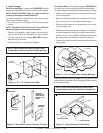
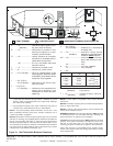
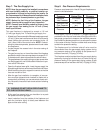
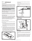
Figure 26. Intermittent Pilot Ignition (IPI) Wiring Diagram
NOTE 1: Ignition module, valve, pilot and wall switch operate on 3 volts.
120 VAC is required at junction box unless equipped with battery back-up.
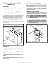
Wall Switch
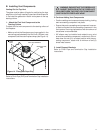
Position the wall switch in the desired position on a wall.
Run a maximum of 25 feet (7.8 m) or less length of 18
A.W.G. minimum wire and connect it to the fireplace ON/
OFF switch pigtails.
WARNING: DO NOT CONNECT 110-120 VAC
TO THE WALL SWITCH OR THE CONTROL
VALVE WILL BE DESTROYED.
CAUTION: LABEL ALL WIRES PRIOR TO DISCONNEC-
TION WHEN SERVICING CONTROLS. WIRING ERRORS
CAN CAUSE IMPROPER AND DANGEROUS OPERA-
TION. VERIFY PROPER OPERATION AFTER SERVICING.
NEUTRAL
GROUND
REMOTE
CONTROL
HOT
LOW VOLTAGE
SEE NOTE 1
ON/OFF
WALL SWITCH
VALVE
BROWN
BROWN
RED
ORANGE
GREEN
BLACK
OPTIONAL
BATTERY
BACK-UP
ORANGE (IGNITOR)
WHITE (SENSOR)
BLACK
GROUND TO
FIREPLACE
CHASSIS
PILOT ASSEMBLY
AND VALVE ASSEMBLY
MUST BE GROUNDED
(COMMON GROUND
WITH FIREPLACE
CHASSIS)
SPARK TO
PILOT IGNITOR
IGNITOR
MODULE
3V
JUNCTION BOX
T
R
A
N
S
F
O
R
M
E
R
3
V
TRANSFORMER OUTLET
PLUG-IN
3V TRANSFORMER
FLAME SPARKER /
SENSOR
LOW VOLTAGE
SEE NOTE 1
OPTIONAL
BATTERY
BACK-UP
IGNITION
MODULE
(3V)
ON/OFF
SWITCH
I
S
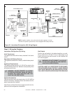
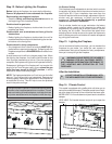
Intermittent Pilot Ignition (IPI) Wiring
3 Volt Transformer
This appliance comes with a factory installed 3 volt trans-
former.
Operation with Battery Back-up
This appliance comes with a factory installed battery back-
up.
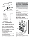
Appliance Requirements
This appliance requires that 110-120 VAC be wired to the
factory installed junction box. Maintain correct polarity when
wiring the junction box.
WARNING: DO NOT CONNECT 110-120 VAC
TO THE GAS CONTROL VALVE OR THE AP-
PLIANCE WILL MALFUNCTION AND THE
VALVE WILL BE DESTROYED.
Optional Accessories
Optional remote control kits require that 110-120 VAC be
wired to the factory installed junction box before the fire-
place is permanently installed.
Heat-Zone and Heat-Out kits are approved with this fire-
place as heat management accessories.
Step 9. Wiring the Fireplace