


Heat & Glo • Escape-42DV • 2052-900 Rev. Y • 11/11 43
D. Electrical Service and Repair
WARNING! Risk of Shock! Label all wires prior to dis-
connection when servicing controls. Wiring errors can
cause improper and dangerous operation. Verify proper
operation after servicing.
WARNING! Risk of Shock! Replace damaged wire with
type 105° C rated wire. Wire must have high temperature
insulation.
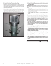
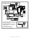
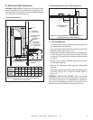
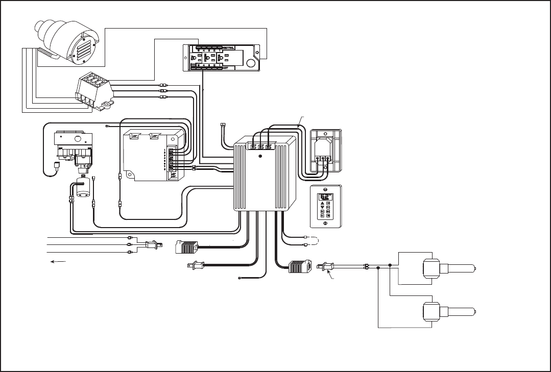
Figure 12.2 IPI Wiring diagram for optional PVK-80 power vent termination cap
(ORANGE)
(GREEN)
GROUND
BLACK
IPI
VALVE
FLAME
SOLENOID
(BLACK)
(WHITE)
(GROUND)
TO HEAT ZONE
FAN
CONNECTION
(BLACK)
(BLACK)
AC
PLUG
FLAME HIGH/LOW
FLAME ON
(RED)
(RED)
(ORANGE)
(ORANGE)
GROUND PIGTAIL
GREEN
JUNCTION BOX
(YELLOW)
(YELLOW)
FACTORY
CONNECTED
TOGETHER
FAN THEMOSTAT
AUX
CONNECTION
(BLACK)
PLUG-ADP
IPI
MODULE
IPI PILOT
3V DC
(BLACK)
(RED)
(BROWN)
(BROWN)
RED
GREEN
YELLOW (H&G)
WHITE (HTL)
REAR VIEW
FRONT VIEW
FIREBOX
BACK
LIGHT 1
BACK
LIGHT 2
R
Y
G
G
Y
R
PVK-80 POWERVENT
(BLACK)
(BROWN)
(RED)
(WHITE)
(WHITE)
(BLACK)
(BROWN)
(RED)
(BROWN)
(BROWN)
(RED)
(BLACK)
(GREEN)
NOTE 1: BROWN AND RED WIRES FROM
PVK-80 ARE FOR THE VACUUM SWITCH
NOTE 2: BLACK, WHITE AND GREEN WIRES
RUN PVK-80 MOTOR.
NOTE 3: GREEN WIRE FROM PVK-80 SHOULD
TIE INTO GROUND A THE JUNCTION BOX
WHERE 110V SERVICE IS REQUIRED.
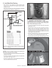
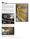
E. Junction Box Installation
If the box is being wired from the INSIDE of the appli-
ance:
• Remove the screw attaching the junction box/receptacle
to the outer shell, rotate the junction box inward to dis-
engage it from the outer shell (see Figure 12.4).
• Pull the electrical wires from outside the appliance through
the opening into the valve compartment and secure wires
with a Romex connector. See Figure 12.4.
• Make all necessary wire connections to the junction
box/receptacle and reattach the junction box/receptacle
to the outer shell.