


Heat & Glo • Escape-42DV • 2052-900 Rev. Y • 11/11 41
A. Wiring Requirements
NOTICE: This appliance must be electrically wired
and grounded in accordance with local codes or, in the
absence of local codes, with National Electric Code
ANSI/NFPA 70-latest edition or the Canadian Electric
Code CSA C22.1.
• Wire the appliance junction box to 110-120 VAC. This is
required for proper operation of the appliance.
• A 110-120 VAC circuit for this product must be protected
with ground-fault circuit-interrupter protection, in
compliance with the applicable electrical codes, when
it is installed in locations such as in bathrooms or near
sinks.
• Low voltage and 110 VAC voltage cannot be shared
within the same wall box.
WARNING! Risk of Shock or Explosion! DO NOT wire
110V to the valve or to the appliance wall switch. Incorrect
wiring will damage controls.
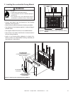
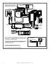
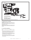
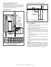
B. IntelliFire Ignition System Wiring
• Wire the appliance junction box to 110 VAC for proper
operation of the appliance.
WARNING! Risk of Shock or Explosion! DO NOT wire
IPI controlled appliance junction box to a switched circuit.
Incorrect wiring will override IPI safety lockout.
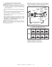
• Refer to Figure 12.1 IntelliFire Pilot Ignition (IPI) Wiring
Diagram.
• This appliance is equipped with an IntelliFire control valve
which operates on a 3 volt system.
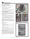
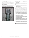
• Plug the 3-volt AC transformer into the appliance junction
box to supply power to the unit OR install two D cell
batteries (not included) into the battery pack before use.
NOTICE: Batteries should not be placed in the battery
pack while using the transformer. Remove batteries before
using the transformer, and unplug the transformer before
installing the batteries. Battery polarity must be correct or
module damage will occur. Batteries should not be placed
in the battery pack until needed.
NOTICE: Do not use battery back up without removing
refractory panels and mesh. Failure to do so may result in
damage to components. Use battery back up to operate
appliance only during power outage.
C. Optional Accessories Requirements
• This appliance may be used with a wall switch or a wall
mounted thermostat.
Wiring for optional Hearth & Home Technologies approved
accessories should be done now to avoid reconstruction.
Follow instructions that come with those accessories.
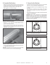
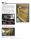
This appliance comes standard with a multi-function
wall switch installed in the unit. A bag containing the wall
switch, cover plate and fl ame control solenoid is located
in the manual bag assembly on the right side of the unit.
Follow the “Determine Location” and “Wiring the Wall
Switch” sections of the WSK-MLT instructions.
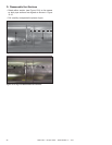
Install the fl ame control solenoid by following Steps 5 - 11
in the “Installing the Control Box” section of the WSK-MLT
instructions.
Also carefully follow the “Setting Flame Height/Manifold
Pressure” section of the included instructions to properly
set the valve pressure. Operating instructions are also in-
cluded in the WSK-MLT instructions.
12
Electrical Information