


8
The Heat-N-Glo Warranty will be voided by, and Heat-N-Glo
disclaims any responsibility for, the following actions:
Installation of any damaged fireplace or vent system
component.
Modification of the fireplace or direct vent system.
Installation other than as instructed by Heat-N-Glo.
Improper positioning of the gas logs or the glass door.
Installation and/or use of any component part not manu-
factured and approved by Heat-N-Glo, not withstanding
any independent testing laboratory or other party approval
of such component part or accessory.
ANY SUCH ACTION MAY POSSIBLY CAUSE A FIRE
HAZARD.
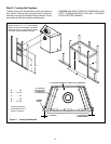
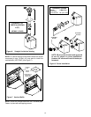
When planning a fireplace installation, its necessary to
determine:
Where the unit is to be installed.
The vent system configuration to be used.
Gas supply piping.
Electrical wiring.
Framing and finishing details.
Whether optional accessoriesdevices such as a fan,
wall switch, or remote controlare desired.
If the fireplace is to be installed on carpeting or tile, or on
any combustible material other than wood flooring, the
fireplace should be installed on a metal or wood panel that
extends the full width and depth of the fireplace.
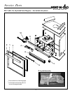
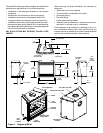
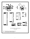
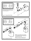
Figure 1. Diagram of BE-41
41
[1043mm]
38
[965mm]
36 1/8
[916mm]
25 ¼
[642mm]
34 5/8
[879mm]
8 5/8
[219mm]
VENT
COLLARS
ELECTRICAL
ACCESS
24 5/8
[625mm]
10 ¼
[259mm]
3 ½
[90mm]
GAS LINE
ACCESS
2 1/8
[55mm]
6 7/8 [174mm]
14 ¼
[362mm]
8 5/8 [219mm]
VENT COLLARS
21 1/2 [548mm]
11 5/8 [297mm]
28 1/2 [724mm]
TOP VENT COLLARS
REAR VENT COLLARS
GAS
LINE
ACCESS
ELECTRICAL
ACCESS
GAS
CONTROLS
RATING PLATE
AND LABELS
LOWER
LOUVER
HOOD
TOP STANDOFFS
TOP
LOUVER