


20
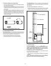
Position the firestops on both sides of the hole previ-
ously cut and secure the firestops with nails or screws.
The heat shields of the firestops MUST BE placed to-
wards the top of the hole.
Continue the vent run through the firestops.
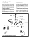
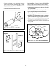
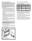
Figure 19. 12" x 12" Hole and Vent Pipe
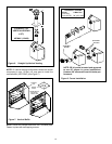
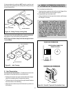
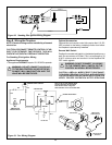
Figure 20. Heat Shield, Interior & Exterior Firestops
VENT PIPE
1" (25.4 mm)
12"
(305mm)
12"
(305mm)
TRIM HEAT
SHIELD IF TOO
LONG, ADD TO
SHIELD IF TOO
SHORT
EXTERIOR
FIRESTOP
INTERIOR
FIRESTOP
HEAT SHIELD
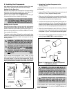
For Vertical Runs - One ceiling firestop is REQUIRED at
the hole in each ceiling through which the vent passes.
To install firestops for vertical runs that pass through ceilings:
Position a plumb bob directly over the center of the verti-
cal vent component.
Mark the ceiling to establish the centerpoint of the vent.
Drill a hole or drive a nail through this centerpoint.
Check the floor above for any obstructions, such as wir-
ing or plumbing runs.
Reposition the fireplace and vent system, if necessary,
to accommodate the ceiling joists and/or obstructions.
Cut an 11-inch X 11-inch (280mm X 280mm) hole through
the ceiling, using the centerpoint previously marked.
Frame the hole with framing lumber the same size as the
ceiling joists.
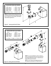
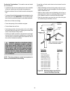
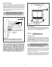
Figure 21. 11" x 11" Hole & New Framing Members
CEILING
NEW
FRAMING
MEMBERS
EXISTING CEILING
JOISTS
CHIMNEY
HOLE
11" (280 mm)
11" (280mm)