


17
Step 3
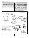
The Gas Control Systems
WARNING: THIS UNIT IS NOT FOR USE WITH
SOLID FUEL.
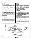
The gas control system used with this model is Standing
Pilot Ignition.
Standing Pilot Ignition System
This system includes millivolt control valve, standing pilot,
thermopile/thermocouple flame sensor, and piezo ignitor.
WARNING: 110-120 VAC MUST NEVER BE
CONNECTED TO A CONTROL VALVE IN A
MILLIVOLT SYSTEM.
AVERTISSEMENT: NE PAS BRÛLER DE
COMBUSTIBLES SOLIDES AVEC CET
APPAREIL DE CHAUFFAGE AU GAZ.
La commande utilisée avec ce modèle est un système
dallumage par veilleuse.
Allumage par veilleuse
Ce système comprend une vanne de commande millivolts,
une veilleuse, un détecteur de flammes thermopile/
thermocouple et un allumeur piézo.
AVERTISSEMENT: DANS UN SYSTÈME
MILLIVOLTS, NE PAS RACCORDER UNE VANNE
DE COMMANDE SUR 110-120 VCA.
!
!
Step 2
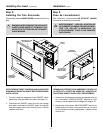
Positioning, Leveling, and
Securing Insert
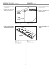
Installing the Insert
(continued)
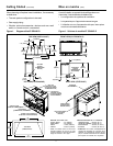
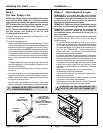
1. Place the insert into position.
2. Level the insert from side to side and from front to back.
If necessary use the legs included in the manual bag.
Screw the legs into the nuts installed in the bottom
rear of the insert. Turn legs in until insert is level.
Étape 2
Mise en place, mise à niveau
et fixation
!
!
Étape 3
Commandes dalimentation en gaz
1. Mettre lappareil de chauffage au gaz en place.
2. Le mettre à niveau latéralement et
longitudinalement.
Au besoin, utiliser les pieds inclus dans le sac de pièces.
Visser les pieds dans les écrous installés en bas et à
larrière de lappareil de chauffage. Tourner les pieds
jusquà ce que lappareil soit horizontal.
Installation (suite)
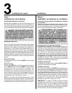
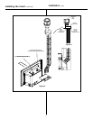
STANDING PILOT
(VEILLEUSE)
Figure 6.
Gas Controls Systems
Figure 6.
Commandes dalimentation en gaz