


12
3
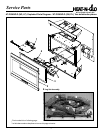
Installing the Insert
Installation
Étape 1
Installation du système de ventilation
Précautions à respecter pour linstallation du système
de ventilation
Avant de commencer la pose des kits de ventilation, lire les
instructions suivantes et les instructions des kits pour as-
surer une installation correcte. Consulter les codes de con-
struction locaux avant de commencer linstallation.
AVERTISSEMENT: CET APPAREIL DE
CHAUFFAGE AU GAZ ET SON SYSTÈME DE
VENTILATION DOIVENT COMMUNIQUER
DIRECTEMENT AVEC LAIR EXTÉRIEUR ET NE
DOIVENT JAMAIS ÊTRE RACCORDÉS À UNE
CHEMINÉE DESSERVANT UN APPAREIL SÉPARÉ
BRÛLANT DES COMBUSTIBLES SOLIDES. CHAQUE
APPAREIL AU GAZ DOIT DISPOSER DUN SYSTÈME
DE VENTILATION SÉPARÉ. LES SYSTÈMES DE
VENTILATION COMMUNS À PLUSIEURS
APPAREILS SONT INTERDITS.
Homologations du système de ventilation
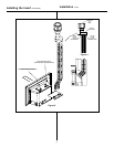
Le tableau 1 et les figures 3 à 5 montrent les systèmes de
ventilation et mitres approuvés pour le modèle présenté dans
ce guide. Les autocollants apposés sur les mitres signalent
lhomologation. Un système de ventilation flexible homologué
de 7,62 cm (3 in.) de diamètre en aluminium ou acier
inoxydable sert à la fois pour les conduits dentrée de lair
de combustion et les conduits de refoulement des gaz
déchappement. NUTILISER AUCUN AUTRE SYSTÈME OU
ÉLÉMENTS DE SYSTÈME. Des notices de montage
détaillées accompagnent chaque kit de mitre et doivent être
utilisées en conjonction avec ce guide.
Ventilation Horizontale
Le système de ventilation de ce modèle NE PEUT PAS se
terminer par une section horizontale.
Ventilation Verticale
Les conduits de ventilation DOIVENT être raccordés aux
colliers appropriés de lappareil de chauffage ET la tuyauterie
des gaz déchappement DOIT être raccordée à la mitre,
sinon lappareil ne peut pas fonctionner. Le conduit dair de
combustion PEUT être raccordé à la mitre ou aboutir à
lintérieur de la cheminée. Cependant, louverture inférieure
de la cheminée doit être scellée autour des tuyaux de
ventilation si le conduit dair de combustion Nest PAS
raccordé à la mitre. Voir les figures 3, 4 et 5.
REMARQUE: La hauteur verticale minimum (conduit
déchappement) est de 4,2 m (14 ft) et la hauteur verticale
maximum est de 15 m (50 ft). Mesurer ces dimensions à
partir des colliers de départ de lappareil de chauffage
jusquau bout de la dernière section de conduits de ventilation.
Voir la dimension V (hauteur verticale) à la figure 3.
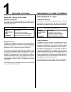
Step 1
Installing the Vent System
Vent System Installation Precautions
Before starting installation of vent kits, the installer should
read these instructions and the Vent Kit Instructions to
ensure that a proper vent installation is completed. Consult
your local Building Codes before beginning the Installation.
WARNING: THIS GAS INSERT AND VENT
ASSEMBLY MUST BE VENTED DIRECTLY TO
THE OUTSIDE AND MUST NEVER BE ATTACHED TO
A CHIMNEY SERVING A SEPARATE SOLID FUEL
BURNING APPLIANCE. EACH GAS APPLIANCE
MUST USE A SEPARATE VENT SYSTEM. COMMON
VENT SYSTEMS ARE PROHIBITED.
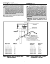
Vent System Approvals
Table 1 and Figure 3 through 5 shows the vent termination
caps and systems approved for the use with these models.
Approved vent system terminations are labeled for
identification. 3-inch diameter listed flexible aluminum or
stainless steel gas vent is used for both the incoming
combustion air and exhaust vent pipes. NO OTHER
VENTING SYSTEMS OR COMPONENTS MAY BE USED.
Detailed installation instructions are included with each vent
termination kit and should be used in conjunction with this
manual.
Horizontal Venting
The vent system on this model CANNOT be terminated
horizontally.
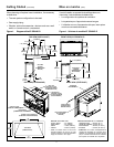
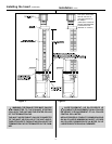
Vertical Venting
The vent pipes MUST be connected to the proper collars on
the unit AND the exhaust vent pipe MUST be connected to
the termination cap or the unit will not operate. The
combustion air vent pipe CAN be connected to the
termination cap or it can terminate inside the chimney. The
bottom opening of the chimney must be sealed around the
vent pipes if the combustion air vent is NOT connected to
the termination cap. See Figures 3, 4 and 5.
NOTE: The minimum vertical rise (exhaust vent) is 14 feet
and the maximum vertical rise is 50 feet. These dimensions
are measured from the starting collars of the unit to the end
of the last section of vent pipe. See dimension V in Figure 3.
!
!