


Heat & Glo • 6000G, 6000G-IPI • 2103-900 Rev. M • 9/0840
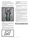
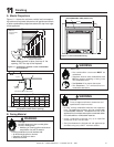
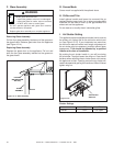
WHT
WHT
BLK
BLK
GRN wire
inside box
Copper
ground attached
to GRN screw with
GRN wire
14/2WG
Romex
Connector
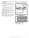
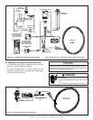
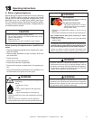
If the box is being wired to a wall
mounted switch for use with a fan (See
Figure 10.5):
• The power supply for the appliance
must be brought into a switch box.
• The power can then be supplied from
the switch box to the appliance using
a minimum of 14-3 with ground wire.
• At the switch box connect the black
(hot) wire and red (switch leg) wire to
the wall switch as shown.
• At the appliance connect the black
(hot), white (neutral) and green
(ground) wires to the junction box as
shown.
• Add a 1/4 inch insulated female con-
nector to the red (switch leg) wire,
route it through the knockout in the
face of the junction box, and connect
to the top fan switch connector (1/4
inch male) as shown.
Red
Red
BlackBlack
Green
Green
White
White
Red
Black
Green
White
SWITCH BOX
JUNCTION BOX
POWER
SUPP LY WIRE S
SWITCH
MINIMUM 14-3 AWG
WITH GROUND
Note: Do NOT wire 110
VAC to wall switch.
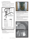
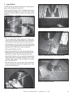
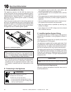
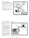
• Remove the screw attaching the junction box/re-
ceptacle to the outer shell, rotate the junction box
inward to disengage it from the outer shell (see
Figure 10.4).
• Pull the electrical wires from outside the appli-
ance through this opening into the valve compart-
ment.
• Feed the necessary length of wire through the
connector.
• Make all necessary wire connections to the junc-
tion box/receptacle and reassemble the junction
box/receptacle to the outer shell.
Figure 10.4 Junction Box Detail
Figure 10.5 Junction Box Wired to Wall Switch
E. Junction Box Installation
F. Wall Switch Installation for Fan (Optional)