


Heat & Glo • 6000G, 6000G-IPI • 2103-900 Rev. M • 9/08 39
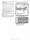
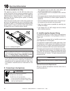
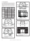
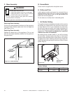
RED
THERMOSTAT
WIREASSEMBLY
BRN
RED
STANDING
PILOT
VALVE
WHT
ON/OFFPIGGYBACK
WIRE
Figure 10.3 Standing Pilot Ignition Wiring Diagram
Figure 10.2 Intellifi re Pilot Ignition (IPI) Wiring Diagram
*Note: Appliance will not operate unless properly grounded.
PLUG-IN
3V TRANSFORMER
ON/OFF
WALL SWITCH
IGNITION
MODULE
(3V)
VALVE
NEUTRAL
GROUND
LOW VOLTAGE
SEE NOTE 1
REMOTE
CONTROL HOT
PLUG-IN
REMOTE
JUMPERWIRE
ORG
GRN
BRN
BRN
RED
BLK
INTERMITTENT
PILOTIGNITOR
ORG
WHT
IGNITION MODULE 3 VAC
TRANSFORMER
VALVE
3 VAC
THERMOSTAT
WIRE
ASSEMBLY
BLACKWIRECAN BE
PLUGGED INTO ANY
OF #1 - #5 LOCATIONS
ON THE HOTSIDE
WHITEWIRE CANBE
PLUGGEDINTO ANY
OF#1 - #5 LOCATIONS
ON THE NEUTRAL SIDE
GROUNDTO
FIREPLACE
CHASSIS*
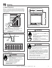
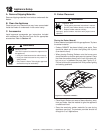
D. Standing Pilot Ignition System Wiring
• This standing pilot ignition system wiring does not
require a 110 VAC supply to operate.
• It is recommended that a 110 VAC junction box be
installed for use with a fan or remote control. (See Figure
10.4 for junction box wiring).
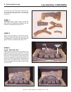
CAUTION
Label all wires prior to disconnection when servicing controls.
Wiring errors can cause improper and dangerous operation.
Verify proper operation after servicing.
Shock hazard.
• Replace damaged wire with type 105º C rated
wire.
• Wire must have high temperature insulation.
WARNING