


9
Heat Controller, Inc. VMH 30/36 SERIES Installation, Operation & Maintenance
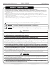
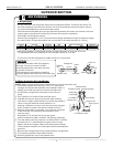
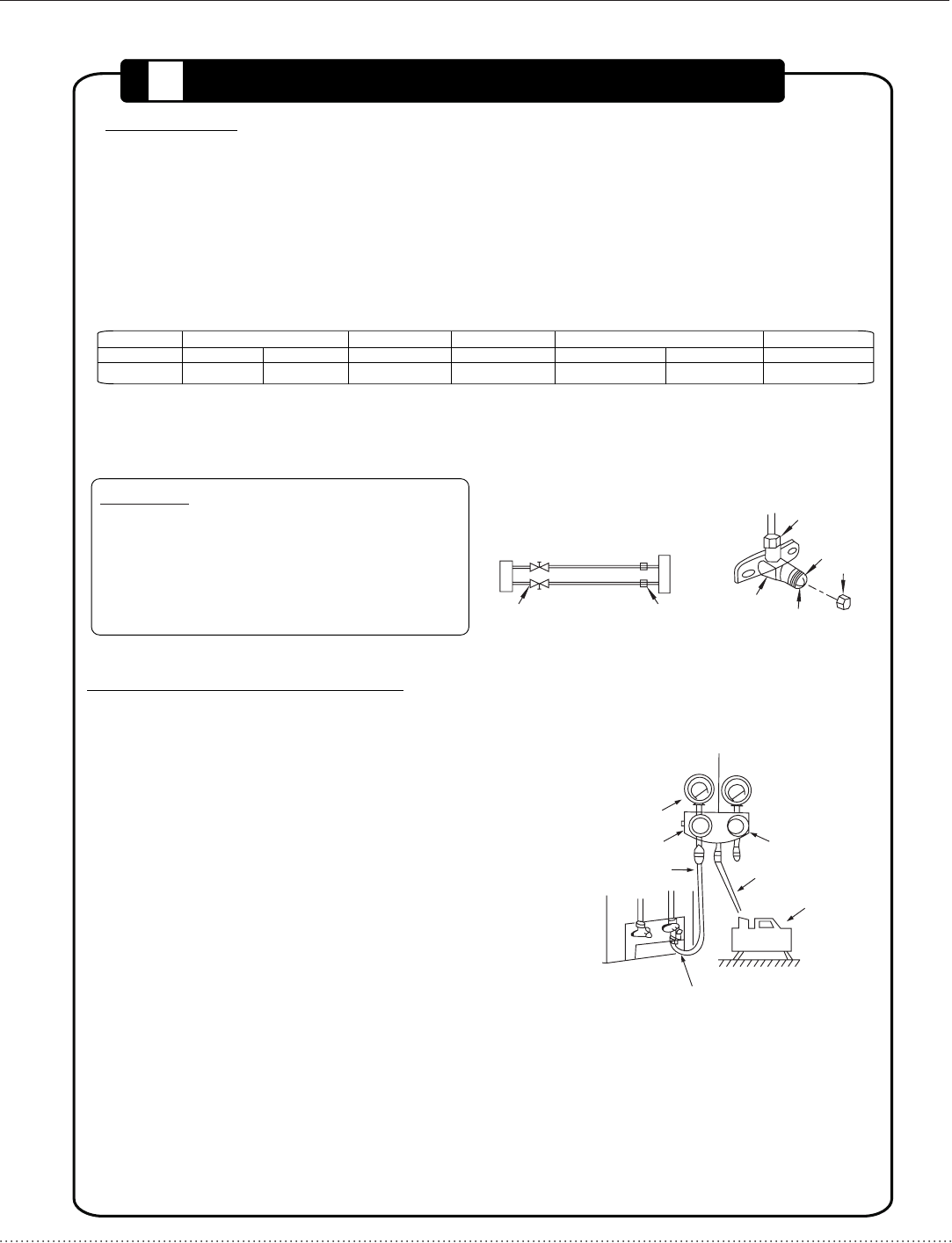
AIR PURGING
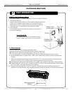
5
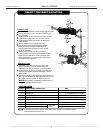
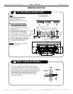
Open the valve stem until it hits against
the stop. Do not try to open it further.
Securely tighten the valve stem cap with
a spanner or wrench.
See tightening torque table on page 8 to
properly tighten and torque the valve stem cap.
Flare nut
Stop
Cap
Valve body
Valve stem
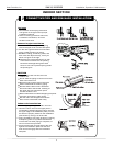
Ensure any R-410A refrigerant is added to the unit in liquid form.
Air and moisture in the refrigerant system have undesirable effects. Therefore, the indoor unit
and tubing between the indoor and outdoor unit must be leak tested and evacuated to remove
any noncondensables and moisture from the system.
Check that each tube(both l
iquid and gas side tubes) between the indoor and outdoor units have
been properly connected and all wiring for the test run has been completed.
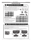
Pipe length and refrigerant amount:
Units are pre-charged for 16.5 ft. (5m) total line set length, additional charge is needed for longer
line sets lengths. Charge adjustments are not required for line sets less than 16.5 ft (5m)
Outdoor
unit
Indoor
unit
Refrigerant
Packed valve
Half union
Gas side
Liquid side
A
C
D
B
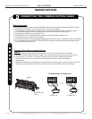
NOTE: Refer to the manifold valve manufacturer’s instructions before use.
1. Completely tighten the flare nuts, A, B, C, D, (see figure
on page 10) connect the manifold valve charge hose to a
cha
rge port of the low pressure valve on the gas side.
2. Connect the charge hose connection to the vacuum
pump.
3. Fully open the handle of the manifold valve.
4. Operate the vacuum pump to evacuate. After starting
evacuation, slightly loose the flare nut of the low pressure
valve on the gas side and check that the air is
entering. (Operation noise of the vacuum pump changes
and a compound meter indicates 0 instead of minus)
5. After the evacuation is complete, fully close the lo handle
of the manifold valve and stop the operation of the
vacuum pump.
Evacuate for 15 minutes and more and check
th
at the compound meter indicates -29.92inHg(-76cmHg).
O
6. Turn the stem of the low pressure valve B about 45 counter-
clockwise for 6~7 seconds after the gas units out, then
tighten the flare nut again. Make sure the pressure display
in the pressure indicator is a little higher than the atmosphere
pressure.
7. Remove the charge hose from the Low pressure charge hose.
8. Fully open the packed valve stems B and A.
9. Securely tighten the cap of the packed valve.
Lo
Manifold valve
Compound meter
-29.92 inHg
*(-76cmHg)
Lo Handle
Hi Handle
Charge hose
Charge hose
Vacuum pump
Pressure gauge
Low pressure valve
1. Air purging
2. When using the Vacuum Pump
CAUTION
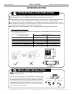
Pipe Size
Gas (in) Liquid (in)
5/8 (16mm) 3/8(9.52mm)
Max
Elevation (ft)
32 (9.75m)
Total Line Length (ft)
Min. Max.
10 (3m) 82 (25m)
Capacity
Btu/h
30-36k
Standard
Length (ft)
*16.5 (5m)
Additional
Refrigerant oz/ft
.4 (40g/m)
*Unit charge located on rating plate includes enough refrigerant for 16.5 feet of line set.
* Charge adjustment is not required on line set lengths less than 16.5 feet.
OUTDOOR SECTION